Anchor rod mounting device

An installation device and bolt technology, which is applied in the directions of support device, bolt installation, drilling equipment, etc., can solve the problems of long construction period and low construction efficiency of bolt installation.

Active Publication Date: 2018-06-29
山西新能正源智能装备有限公司
View PDF5 Cites 31 Cited by
  • Summary
  • Abstract
  • Description
  • Claims
  • Application Information

AI Technical Summary

Problems solved by technology

[0003] The purpose of this disclosure is to provide a bolt installation device to solve the problems of long construction period and low construction efficiency of bolt installation

Method used


Image

  • Anchor rod mounting device
  • Anchor rod mounting device
  • Anchor rod mounting device

Examples


Embodiment Construction

[0024] Specific embodiments of the present disclosure will be described in detail below in conjunction with the accompanying drawings. It should be understood that the specific embodiments described here are only used to illustrate and explain the present disclosure, and are not intended to limit the present disclosure.

[0025] In this disclosure, unless stated otherwise, the orientation words used such as "inner" and "outer" are for the contours of the corresponding parts; "front" and "rear" are defined according to usage habits Specifically, the direction of movement of the power head during drilling is the front, and the reverse direction is the rear; the terms "first", "second", etc. used in this disclosure are to distinguish one element from another, not sequence and importance. In addition, in the following description, when drawing is used for drawing, the same code|symbol in different drawing represents the same element.

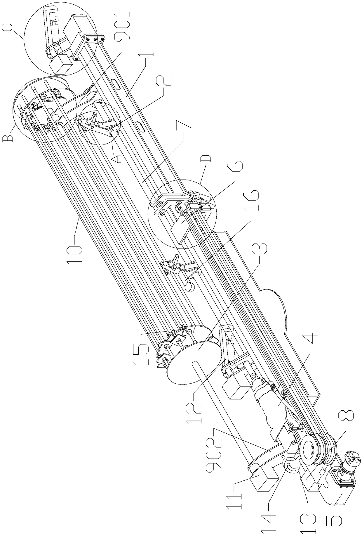
[0026] Such as figure 1 As shown, the bolt...


PUM


Abstract

The invention relates to an anchor rod mounting device which comprises a thrusting beam, a power head, a first driving part, anchor rod storage portions and anchor rod clamping components. The power head is slidably mounted on the thrusting beam, the first driving part is used for driving the power head to slide along the thrusting beam, the anchor rod storage portions are fixed onto one side of the thrusting beam and used for placing a plurality of anchor rods, a recognizable label is arranged on each anchor rod, and the anchor rod clamping components are rotatably mounted on one side of thethrusting beam and used for placing the anchor rods of the anchor rod storage portions at the front end of the power head in a clamping manner, so that the anchor rods can be pushed by the power head.The anchor rod mounting device is integrated on a drilling machine, the anchor rod clamping components can place the anchor rods at the front end of the power head in a clamping manner after holes are drilled by the drilling machine, and the push force of the power head pushes the anchor rods to enter anchor rod holes. The recognizable label is arranged on each anchor rod, and information and mounting positions of the anchor rods can be accurately acquired when a reading device capable of recognizing the recognizable labels approaches to the anchor rods.

Description

technical field [0001] The present disclosure relates to the field of tunnel engineering machinery, in particular, to a bolt installation device. Background technique [0002] During the construction of the tunnel, at first the drilling rig is used to drill holes in the rock mass, then the anchor rods are put into the drilled holes, and then the anchor rod holes are grouted. In the specific implementation, the three-arm rock drilling rig is usually used to drill the bolt holes, and then the bolts are manually installed and fastened, and then the wet spraying machine is used for grouting. In this process, there are many problems such as long construction period of multiple equipment operations and low construction efficiency. Contents of the invention [0003] The purpose of the present disclosure is to provide a bolt installation device to solve the problems of long construction period and low construction efficiency of bolt installation. [0004] In order to achieve the...

Claims


Application Information

Patent Timeline
Patent Type & Authority Applications(China)
IPC IPC(8): E21D20/00E21B15/00
CPCE21B15/00E21D20/003Y02E10/72
Inventor 江乃东管永昌
Owner 山西新能正源智能装备有限公司
Why Eureka
Try Eureka