Centrifugal type friction damper

A friction damper, centrifugal technology, applied in friction dampers and other directions, can solve the problems of oil leakage, hydraulic damper damping force and temperature, etc.

Inactive Publication Date: 2018-06-29
GUIZHOU HUAFENG ELECTRICAL APPLIANCES
View PDF9 Cites 2 Cited by
  • Summary
  • Abstract
  • Description
  • Claims
  • Application Information

AI Technical Summary

Problems solved by technology

[0002] Hydraulic dampers are often used in traditional mechanical transmission applications, but hydraulic dampers have th

Method used


Image

  • Centrifugal type friction damper
  • Centrifugal type friction damper

Examples


Embodiment Construction

[0013] Below in conjunction with accompanying drawing, the present invention will be further described:

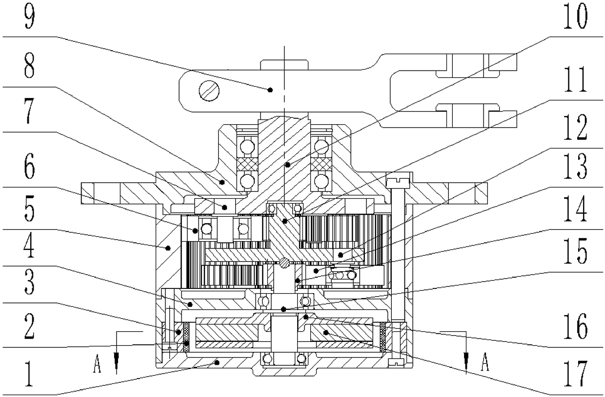
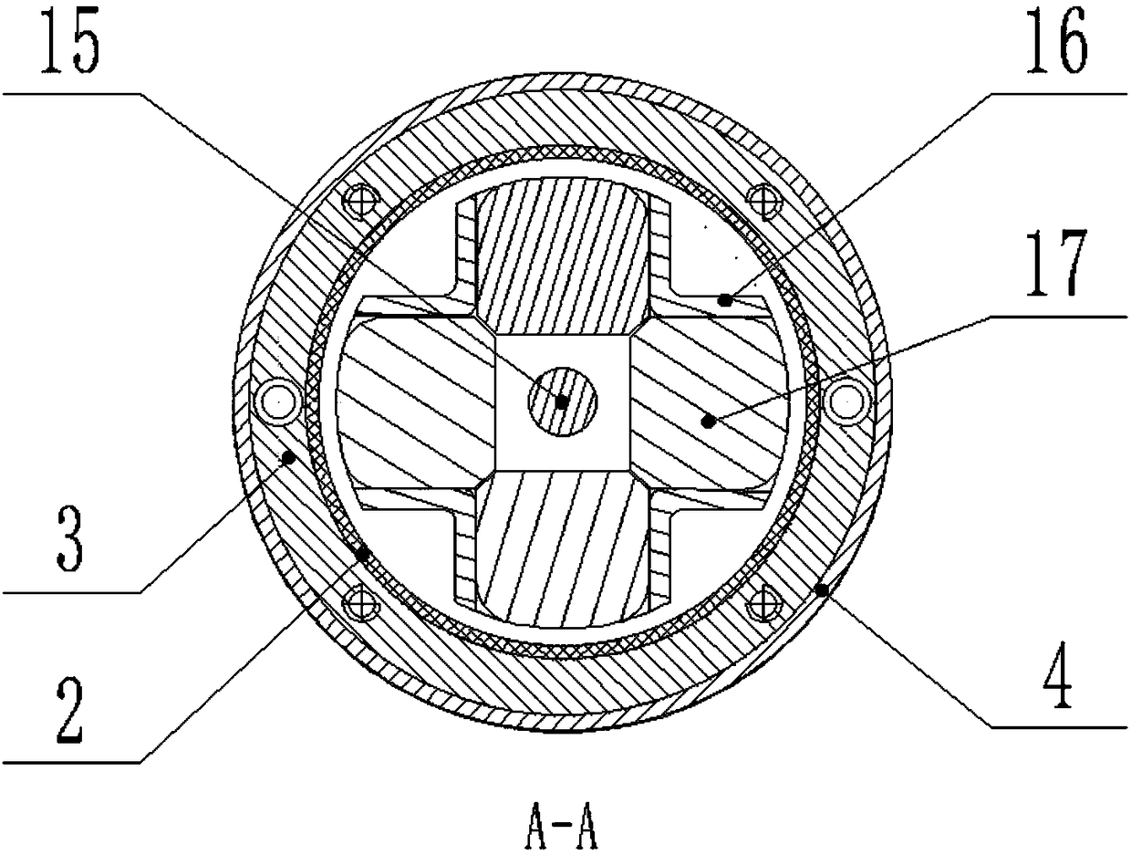
[0014] The centrifugal friction damper is characterized in that: the damper includes a two-stage planetary speed increase, the input shaft 10 is supported and fixed on the front end cover 8, and three pin shafts 7 are pressed on the input shaft 10, and three planetary gears 6 are installed through bearings , the three planetary gears 6 mesh with the inner ring gear 5 and the outer ring teeth of the planetary carrier 11 at the same time, and the three planetary gears 6, the inner ring gear 5 and the outer ring teeth of the planetary carrier 11 form a first-stage planetary gear speed-up; the planetary carrier 11 There are three pin shafts 12 on the upper press, and three planetary gears 13 are installed through the bearings. The three planetary gears 13 mesh with the ring gear 5 and the shaft gear 14 at the same time. The three planetary gears 13, the ring gear 5 and the shaf...


PUM


Abstract

The invention relates to the technical field of mechanical transmission devices, in particular to a centrifugal type friction damper. The centrifugal type friction damper is composed of two parts of abraking ring and a centrifugal rotor, the centrifugal rotor comprises a rotor shaft, a centrifugal block support and a centrifugal block, a shaft gear is installed on the rotor shaft, the braking ring comprises a fixed ring and nitrile rubber bonded and connected to the surface of an inner hole of the fixed ring, the centrifugal rotor is assembled inside a bearing chamber of a shell body througha bearing at one end of the rotor shaft, the bearing at the other end of the rotor shaft is assembled inside the bearing chamber of a rear end cover, and the braking ring is installed and fixed on theinner cavity of the shell body through bolts. The centrifugal type friction damper is small in volume and compact in structure, no extra energy is needed, particularly, compared with an existing hydraulic damper, the oil-leakage problem does not exist, and the centrifugal type friction damper is convenient to install, use and maintain.

Description

technical field [0001] The invention relates to the technical field of mechanical transmission devices, in particular to a centrifugal friction damper. Background technique [0002] Hydraulic dampers are often used in traditional mechanical transmission applications, but hydraulic dampers have the disadvantages of damping force being greatly affected by temperature and oil leakage. Contents of the invention [0003] Purpose of the invention: In order to prevent high-speed impact during mechanical manipulation, suppress vibration, and achieve the effect of damping and shock absorption, the present invention proposes a centrifugal friction damper. [0004] Technical solutions: [0005] A centrifugal friction damper, which consists of two parts: a brake ring and a centrifugal rotor. The centrifugal rotor includes a rotor shaft, a centrifugal block bracket, and a centrifugal block. A shaft gear is installed on the rotor shaft. The brake ring includes a fixed ring The centrif...

Claims


Application Information

Patent Timeline
IPC IPC(8): F16F7/06
CPCF16F7/06
Inventor 许彪梁海峰林杨林立许小林卢艳
Owner GUIZHOU HUAFENG ELECTRICAL APPLIANCES
Why Eureka
Try Eureka