Pinch valve

A technology of pinch valves and tubular valves, which is applied in the field of pinch valves, can solve problems such as wear and tear, and achieve the effects of improving precision, improving sealing functions, and increasing sealing force

Active Publication Date: 2018-06-29
FESTO AG & CO KG
View PDF8 Cites 8 Cited by
  • Summary
  • Abstract
  • Description
  • Claims
  • Application Information

AI Technical Summary

Problems solved by technology

[0004] It is disadvantageous in the known prior art that relatively s

Method used


Image

  • Pinch valve
  • Pinch valve
  • Pinch valve

Examples


Embodiment Construction

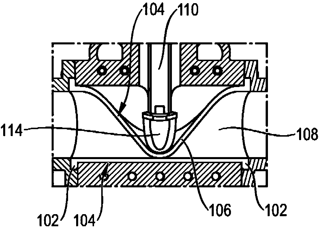
[0033] figure 1 A schematic diagram of a prior art pinch valve is shown. The pinch valve includes a valve member 106 that defines a flow passage 108 for fluid as a tubular member. A tubular valve member is arranged between two connecting elements 102 and comprises a flexible peripheral wall 104 . The pinch valve comprises a closure device 110 disposed on the outside of the peripheral wall 104 and designed to be switchable between an open position in which the flow channel 108 defines a state through which fluid can flow, and a closed position in which In the closed position, the flow channel 108 defines a closed state for fluid. The closure device 110 comprises a plunger element 114 designed to be switchable between an open position and a closed position by a translational movement. The closure device 110 comprises only a single plunger element 114, with the result that the tubular valve member 106 is subjected to particularly large deformations as well as large mechanical ...


PUM


Abstract

The invention relates to a pinch valve (100), comprising a tubular valve member (106), which has a flexible peripheral wall (104) and defines a flow channel (108) for a fluid between two connection elements (102), and a closing device (110) arranged outside the peripheral wall (104), which is switchable between an open position where the flow channel (108) defines a fluid-permeable state, and a closed position where the flow channel (108) defines a fluid-closed state, characterized in that the closing device (110) has a stopping block (112) which restricts the transfer of the closing device (110) to the closed position.

Description

technical field [0001] The invention relates to a pinch valve having a tubular valve member extending between two connecting elements and having a flexible peripheral wall defining a flow channel for a fluid and having closure means arranged in The exterior of the peripheral wall is between an open position in which the flow channel defines a condition through which fluid can flow and a closed position in which the flow channel defines a condition closed to fluid. Background technique [0002] A pinch valve with a valve housing is known from document DE 10 2007 006 764 B3, wherein a tubular valve member with a flexible peripheral wall extends between two fluid connectors, the peripheral wall of the tubular valve member being able to span the The longitudinal axis is extruded to vary the flow cross-section and is surrounded by a rigid support tube limiting its radial widening, through which the tubular valve member is assembled to a cylindrical structure replaceably inserted ...

Claims


Application Information

Patent Timeline
IPC IPC(8): F16K7/06F16K31/44
CPCF16K7/06F16K31/44F16K7/065
Inventor M·穆勒
Owner FESTO AG & CO KG
Why Eureka
Try Eureka