
Optical device for plant illumination and plant cultivation device comprising the optical device

An optical device and plant lighting technology, applied in the parts of lighting devices, lighting devices, lighting auxiliary devices, etc., can solve the problems of uneven light intensity distribution, affecting plant quality, low space utilization, etc., and improve energy utilization. efficiency, improve planting quality, and reduce light waste

Active Publication Date: 2021-02-12
FUJIAN SANAN SINO SCI PHOTOBIOTECH CO LTD
View PDF4 Cites 0 Cited by
  • Summary
  • Abstract
  • Description
  • Claims
  • Application Information

AI Technical Summary

Problems solved by technology

The thermal light source has serious infrared radiation and high calorific value, which not only consumes more energy, but also can only be installed far above the plants in order to avoid the impact of the high temperature generated by the lamp on the plants, resulting in low space utilization
[0004] In addition, the existing optical devices for plant lighting, whether using high-pressure sodium lamps or other thermal light sources, have a center light intensity that is stronger than the light intensity on both sides, and the light intensity distribution is uneven, which affects the quality of plants.

Method used


Image

  • Optical device for plant illumination and plant cultivation device comprising the optical device
  • Optical device for plant illumination and plant cultivation device comprising the optical device
  • Optical device for plant illumination and plant cultivation device comprising the optical device

Examples


Embodiment Construction

[0032] Before further describing the specific embodiments of the present invention, it should be understood that the protection scope of the present invention is not limited to the following specific specific embodiments; it should also be understood that the terms used in the examples of the present invention are to describe specific specific embodiments, It is not intended to limit the protection scope of the present invention; in the description and claims of the present invention, unless the context clearly indicates otherwise, the singular forms "a", "an" and "the" include plural forms.

[0033] When the examples give numerical ranges, it should be understood that, unless otherwise stated in the present invention, the two endpoints of each numerical range and any value between the two endpoints can be selected. Unless defined otherwise, all technical and scientific terms used herein have the same meaning as commonly understood by one of ordinary skill in the art. In addit...


PUM


Abstract

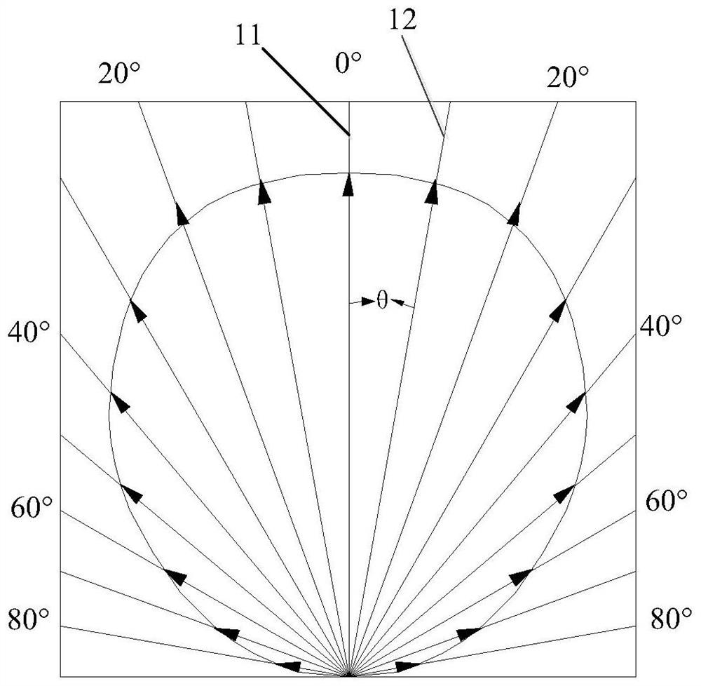
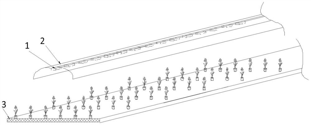
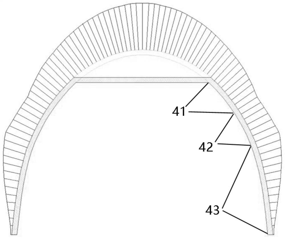
The present invention relates to the technical field of plant lighting, and specifically provides an optical device for plant lighting, which is set at a preset position above the center line of the planting area; including: a reflector and an LED lamp located at the center inside the reflector; wherein, the The reflector is a symmetrical structure; one side from the highest reflection point to the lowest reflection point includes the first section, the second section, and the third section adjacent in turn; in the direction from the highest reflection point to the lowest reflection point, the first section The curvature of the first segment gradually decreases, the curvature of the second segment gradually increases, and the curvature of the third segment gradually decreases. The optical device for plant lighting provided by the present invention can reflect the light beyond the planting area to the planting area, and supplement the illumination on both sides of the center line of the illumination, avoiding the phenomenon of light waste, improving the energy utilization rate, and improving the efficiency of the planting area. The uniformity of illumination improves the quality of planting in the planting area.

Description

technical field [0001] The invention relates to the technical field of plant lighting, in particular to an optical device for plant lighting and a plant cultivation device comprising the optical device. Background technique [0002] At present, in the field of agriculture, economic benefits are improved through intensive planting, for example, making full use of space to increase the area that can be planted. The light source for plant lighting is one of the bottlenecks of intensive planting. [0003] The light source used in the optical device for plant lighting is generally a thermal light source, such as a high-pressure sodium lamp. The thermal light source has serious infrared radiation and high calorific value, which not only consumes more energy, but also can only be installed far above the plants in order to avoid the impact of the high temperature generated by the lamp on the plants, resulting in low space utilization. [0004] In addition, in the existing optical ...

Claims


Application Information

Patent Timeline
Patent Type & Authority Patents(China)
IPC IPC(8): F21S8/00F21V13/04F21V19/02A01G7/04F21Y115/10
CPCA01G7/045F21S8/00F21V13/04F21V19/02F21Y2115/10Y02P60/14F21V21/30F21V7/09A01G9/249F21Y2103/10F21S2/005F21V17/101F21V7/0066F21V17/08F21V5/048F21V17/12F21V7/005F21V21/14F21V5/04F21W2131/109
Inventor 伍婵娟曾亮林平秋冯福琳陈莹莹
Owner FUJIAN SANAN SINO SCI PHOTOBIOTECH CO LTD
Learn More