Method for optimizing central wavelength of optical filter of lithography machine

An optimization method and center wavelength technology, applied in microlithography exposure equipment, optomechanical equipment, optics, etc., can solve the problems of high light intensity, difficult processing of narrow-band filters, difficulty in determining filters, etc., and achieve high performance ratio Effect

Inactive Publication Date: 2018-06-29
上海矽越光电科技有限公司
View PDF0 Cites 0 Cited by
  • Summary
  • Abstract
  • Description
  • Claims
  • Application Information

AI Technical Summary

Problems solved by technology

[0003] Under the current circumstances, in the lithography machine, the optical filters are placed in the direction perpendicular to the light. The processing of the narrow-band filter of the lithography machine is very difficult, and the central wavelength of many products often appears to be different. Just at the 365nm position, so that the filter is installed on the lithography machine, which will cause the lithography machine to be unable to obtain the highest light intensity and thus cannot obtain the fastest production speed
Therefore, it is necessary to use the angle at which the narrow-band filter is placed in the lithography machine to obtain the maximum light intensity, but it is very difficult to determine the specific angle of the filter, and it is often only roughly estimated, and then the filter The light sheet is locked at the estimated angle, but the most accurate angle cannot be obtained

Method used


Image

  • Method for optimizing central wavelength of optical filter of lithography machine
  • Method for optimizing central wavelength of optical filter of lithography machine
  • Method for optimizing central wavelength of optical filter of lithography machine

Examples


Embodiment Construction

[0017] In order to make the object, technical solution and advantages of the present invention clearer, the present invention is described below through specific embodiments shown in the accompanying drawings. It should be understood, however, that these descriptions are exemplary only and are not intended to limit the scope of the present invention. Also, in the following description, descriptions of well-known structures and techniques are omitted to avoid unnecessarily obscuring the concept of the present invention. The technical scheme of the present embodiment is as follows:

[0018] A method for optimizing the central wavelength of a photolithography machine filter, the steps are as follows:

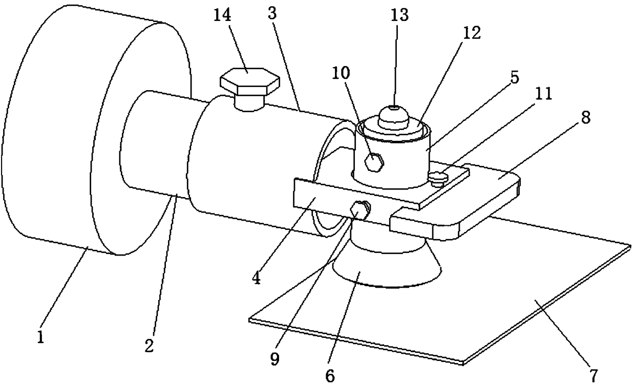
[0019] a. Install the filter on the angle adjustment device, the angle adjustment device includes: stepper motor 1, angle adjustment drive shaft 2, installation sleeve 3, support plate 4, adsorption cylinder 5, adsorption rubber tip 6. Optical filter 7, light intensity sensor 8, ...


PUM


Abstract

The invention discloses a method for optimizing the central wavelength of the optical filter of a lithography machine. The method comprises following steps: step a, installing an optical filter on anangle adjusting device; and step b, starting the angle adjusting device to rotate the optical filter to a certain angle. By changing the placement angle of the narrow band optical filter in a lithography machine, the central wavelength can be changed by 6 nm. Before a lithography machine leaves a factory, an angle that the narrow band optical filter needs to deflect in the lithography machine is provided; a narrow band optical filter with a central wavelength greater than 365 nm in the lithography machine can reach the effect of an optical filter with a central wavelength close to 365 nm; andat the same time, the lithography machine that uses the optical filter can reach a maximal performance ratio.

Description

technical field [0001] The invention belongs to the field of integrated circuit manufacturing, and in particular relates to a method for optimizing the central wavelength of a photolithography machine filter. Background technique [0002] I-line (that is, light with a wavelength near 365nm) lithography machine needs to use a 365nm filter. The 365nm filter is used to filter other wavelengths of light that are harmful to the product except 365nm (such as 365±3nm), and Obtain the highest possible light intensity so that there will be a higher production speed, [0003] Under the current circumstances, in the lithography machine, the optical filters are placed in the direction perpendicular to the light. The processing of the narrow-band filter of the lithography machine is very difficult, and the central wavelength of many products often appears to be different. Just at the 365nm position, if the filter is installed on the lithography machine, it will cause the lithography mac...

Claims


Application Information

Patent Timeline
Patent Type & Authority Applications(China)
IPC IPC(8): G03F7/20
CPCG03F7/70316G03F7/70491
Inventor 方凤云黄凯胡坤
Owner 上海矽越光电科技有限公司
Why Eureka
Try Eureka