A cooling device for computing equipment

A cooling device and hollow technology, applied in computing, instrumentation, electrical and digital data processing, etc., can solve problems such as loss of heat exchange efficiency, large fluid resistance between fins, and overflow of working fluid, and achieve the effect of improving heat exchange efficiency.

Active Publication Date: 2021-02-26
COOLER MASTER SHANGHAI TECH CO LTD
View PDF7 Cites 0 Cited by
  • Summary
  • Abstract
  • Description
  • Claims
  • Application Information

AI Technical Summary

Problems solved by technology

[0004] The present invention provides a cooling device for computing equipment to solve the problem in the prior art that the fluid resistance in the fin gap is relatively large, causing the working fluid to overflow and reducing the heat exchange efficiency

Method used


Image

  • A cooling device for computing equipment
  • A cooling device for computing equipment
  • A cooling device for computing equipment

Examples


Embodiment 1

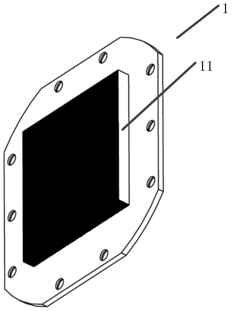
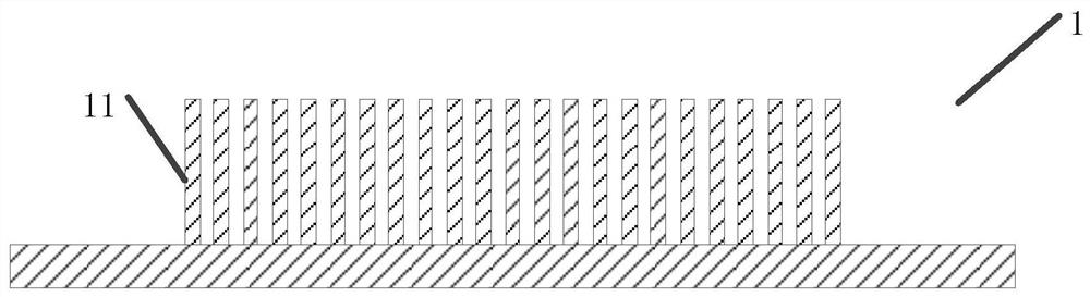
[0076] figure 1 It is a schematic diagram of the three-dimensional structure of the bottom plate of Embodiment 1 of the present invention, such as figure 1 As shown, the base plate 1 is provided with a fin array 11 . The bottom plate 1 is entirely made of heat-conducting materials, such as metal heat-conducting materials such as copper and aluminum or non-metal heat-conducting materials such as graphite. The fin array 11 is also made of the above-mentioned thermally conductive material, and the fin array 11 and the bottom plate 1 can be integrally formed. figure 2 It is a schematic cross-sectional structure diagram of the bottom plate of Embodiment 1 of the present invention, such as figure 2 As shown, a plurality of fins perpendicular to the base plate 1 and parallel to each other form a fin array 11 .

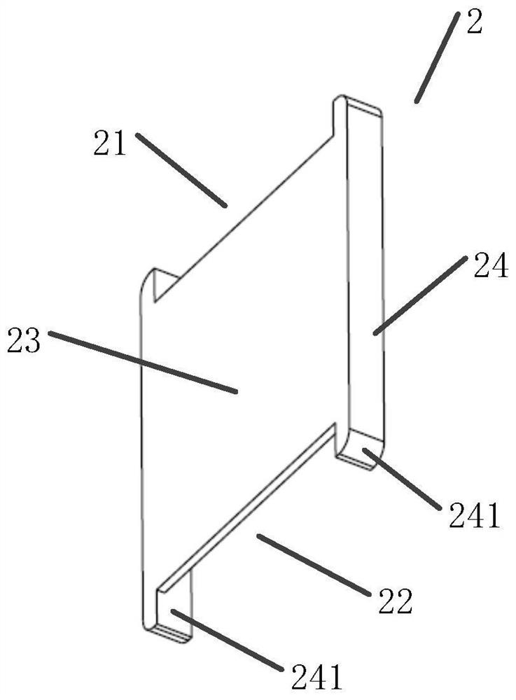
[0077] image 3 It is a schematic diagram of the three-dimensional structure of the restrictor plate in Embodiment 1 of the present invention, Figure 4 It is a schema...

Embodiment 2

[0104] The technical solution of the second embodiment of the present invention is basically the same as the technical solution of the first embodiment of the present invention, the difference lies in the specific structures of the cover and the first casing.

[0105] Figure 22 It is a schematic diagram of the bottom structure of the cover body in Embodiment 2 of the present invention, Figure 23 It is a schematic diagram of the top view structure of the cover body according to the second embodiment of the present invention, such as Figure 22 with Figure 23 As shown, the cover body of the second embodiment of the present invention is provided with a first opening 35 , a second opening 36 , a seventh opening 310 and an eighth opening 311 ; the first hollow structure 33 is also provided with a third groove 312 .

[0106] The first opening 35 is located in the middle of the first hollow structure 33, the second opening 36, the seventh opening 310 and the eighth opening 311 a...

Embodiment 3

[0112] The technical solution of the third embodiment of the present invention is basically the same as the technical solution of the first embodiment of the present invention, the difference lies in the specific structures of the cover and the first casing.

[0113] Figure 26 It is a schematic view of the structure of the cover body in Embodiment 3 of the present invention, Figure 27 It is a schematic diagram of the top view structure of the cover body of the third embodiment of the present invention, as Figure 26 with Figure 27 As shown, the cover body 3 of the third embodiment of the present invention is provided with: a second opening 36 and an eighth opening 311 .

[0114] The second opening 36 and the eighth opening 311 are arranged on the edge of the first hollow structure 33; the second opening 36 communicates with the second groove 32, and the eighth opening 311 communicates with the first Groove 31.

[0115] Figure 28 It is a schematic bottom view of the fi...


PUM


Abstract

The cooling device for computing equipment provided by the present invention includes: a base plate, a flow limiting plate and a cover body; the cover body is provided with a first hollow structure, the base plate is provided with a fin array, and the fin array is placed In the first hollow structure; the first hollow structure is provided with a first groove and a second groove, and the first groove is arranged opposite to the second groove; the restrictor plate is arranged on the between the fin array and the cover; the restrictor plate is provided with a first gap and a second gap; the first groove communicates with the fin array through the first gap, the The second groove communicates with the fin array through the second gap. The cooling device for computing equipment provided by the invention can avoid the overflow of the working fluid caused by the large water flow resistance in the gap between the fins, and improve the heat exchange efficiency.

Description

technical field [0001] The invention relates to the technical field of circulation heat dissipation, in particular to a cooling device for computing equipment. Background technique [0002] With the improvement of the processing speed and performance of the central processing unit (CPU), the heat generated by the current CPU increases, and the high temperature generated by it will shorten the life of the CPU, especially when the excessive heat cannot be effectively removed, it is easy to cause The computer system is unstable. In order to solve the problem of overheating of the CPU, a water cooling device is generally used to cool the CPU so as to maintain the normal operation of the CPU. [0003] Existing water-cooling equipment often adopts the following structure: the bottom plate of the heat exchange chamber is provided with fins, the bottom plate of the heat exchange chamber is attached to the CPU and the heat exchange chamber is connected to the pump, and the pump prov...

Claims


Application Information

Patent Timeline
Patent Type & Authority Patents(China)
IPC IPC(8): G06F1/20
CPCG06F1/20
Inventor 陈振伟魏祐得
Owner COOLER MASTER SHANGHAI TECH CO LTD
Why Eureka
Try Eureka