
A Sampling System Based on Optical Fiber Series

A sampling system and optical fiber technology, applied in the transmission system, optical fiber transmission, electromagnetic wave transmission system, etc., can solve the problems of communication reliability, high cost, and many communication optical fibers, and achieve the effect of improving control performance and reliability

Active Publication Date: 2019-08-30
NR ELECTRIC CO LTD +1
View PDF6 Cites 0 Cited by
  • Summary
  • Abstract
  • Description
  • Claims
  • Application Information

AI Technical Summary

Problems solved by technology

[0005] The purpose of the present invention is to provide a sampling system based on optical fiber series, on the one hand to solve the problem of many communication fibers between the sampling board and the sampling receiving board in the distributed sampling system, complex structure and high cost, and on the other hand to solve the problem of sampling system Sampling synchronization problem; and ensure that when any board or group of optical fibers in the system fails, it will not affect other boards to send and receive sampling data messages, and solve the communication reliability problem of the sampling system

Method used


Image

  • A Sampling System Based on Optical Fiber Series
  • A Sampling System Based on Optical Fiber Series

Examples


Embodiment Construction

[0026] Embodiments of the present invention will be described in detail below in conjunction with the accompanying drawings.

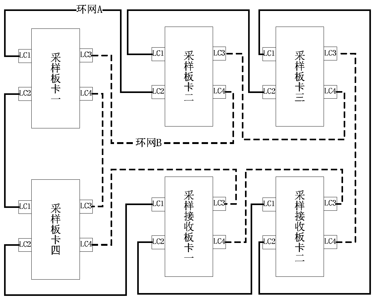
[0027] Such as figure 1 As shown, both the sampling board and the sampling receiving board in the sampling system have optical fiber transceiver interfaces with four LC ports, namely LC1, LC2, LC3, and LC4. LC1 and LC2 form a group, and LC3 and LC4 form a group. Connect the LC1 port of the sampling board with the LC2 port of the previous board through the optical fiber, connect the LC2 port of the sampling board with the LC1 of the next board, and connect all the sampling boards and hosts in series in this way to form an A Ring. Connect the LC3 port of the sampling board with the LC4 port of the previous board through the optical fiber, connect the LC4 port of the sampling board with the LC3 of the next board, and connect all the sampling boards and sampling receiving boards in series in this way Together they form the B ring network. The sampling ...


PUM


Abstract

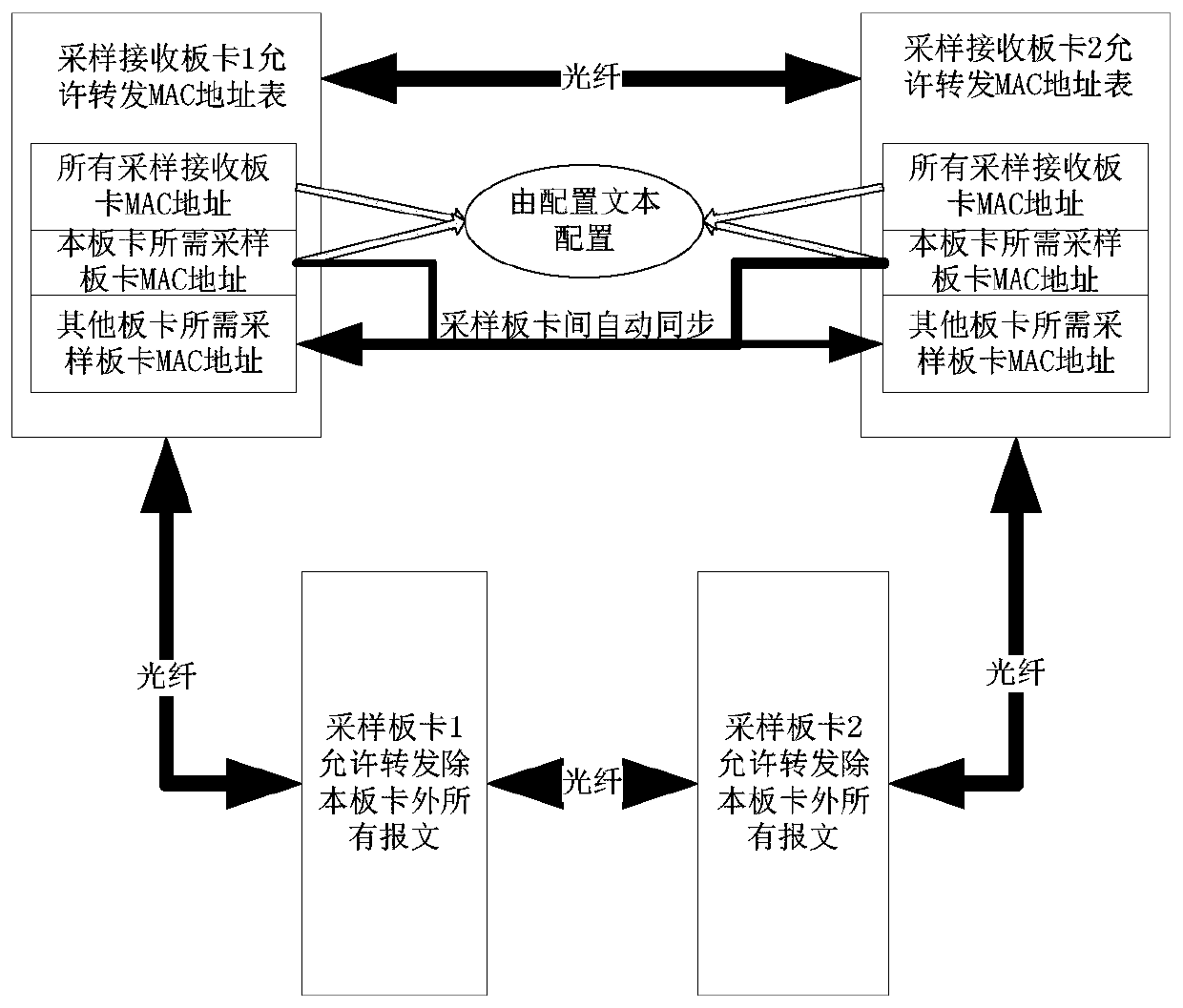
The invention discloses a sampling system based on optical fiber series. The sampling system is composed of multiple sampling boards, and the sampling boards and sampling receiving boards are connected in series through the end of the optical fiber to form a two-way ring network. The sampling data message of the sampling board can be transmitted bidirectionally in the optical fiber ring network, and the failure of any board card will not affect the sending and receiving of messages of other boards. The system can form two completely independent A and B ring networks, and the redundant structure of A and B networks can improve the reliability of the sampling system. The sampling system with optical fiber series structure can effectively reduce the number of optical fibers used, which not only reduces the complexity of system networking, but also effectively reduces costs. Each sampling receiving board can automatically synchronize the MAC address of the sampling board that is allowed to send messages in the ring network. Each sampling receiving board only needs to configure the MAC address of the sampling board it needs to receive, reducing the dependence between sampling boards It is convenient for later upgrade and maintenance. The sampling system can realize synchronous sampling of all sampling boards.

Description

technical field [0001] The invention belongs to the field of electric power system relay protection, in particular to a sampling system based on optical fiber series. Background technique [0002] The UHV DC transmission control and protection system needs to collect a large number of electrical quantities related to voltage and current, such as DC field and AC field, and calculate the timing of the ignition pulse of the converter valve through these electrical quantities and the set target value, so as to control the AC and DC currents. Mutual conversion according to the intended target. The electrical quantities of the traditional control and protection system are sampled by the voltage and current sampling boards distributed in each panel cabinet and converted into digital signals, and then the digital signals are sent to the sampling receiving board of the control and protection host through optical fibers or cables. The optical fibers between the sampling board and the...

Claims


Application Information

Patent Timeline
Patent Type & Authority Patents(China)
IPC IPC(8): H02H1/00H04B10/25H04B10/275H04B10/40H04L29/08H04L29/12H04B10/032
CPCH02H1/00H04B10/032H04B10/25H04B10/275H04B10/40H04L65/40H04L61/00
Inventor 仲浩文继锋周强赵天恩周谷庆
Owner NR ELECTRIC CO LTD
Learn More