

Energy reversible traction substation, method and system
A traction substation and energy technology, which is applied in the direction of converting equipment, electrical components, and AC power input into DC power output with reversible, can solve the problem of train regenerative braking energy waste, etc.
- Summary
- Abstract
- Description
- Claims
- Application Information
AI Technical Summary
Problems solved by technology
Method used
Image

Examples
Embodiment Construction
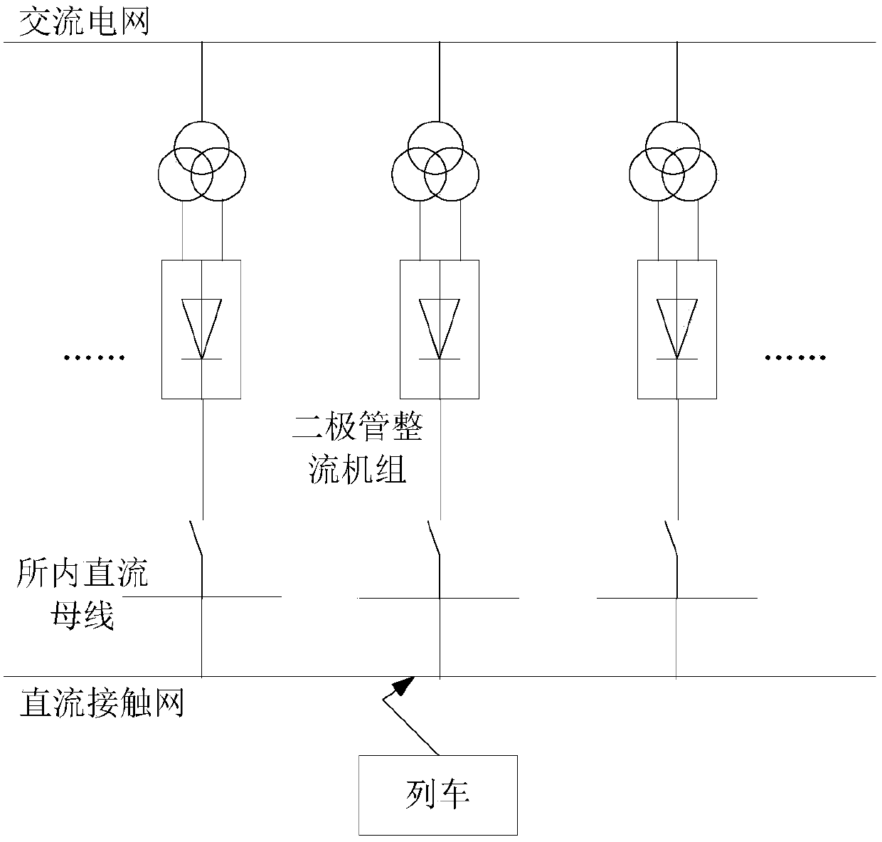
[0050] Usually, an urban rail transit traction power supply system includes an AC grid, a DC catenary, and multiple traction substations, and each traction substation includes a diode rectifier unit. Such as figure 1 As shown, for the convenience of description, a traction substation is taken as an example to describe this embodiment in detail.
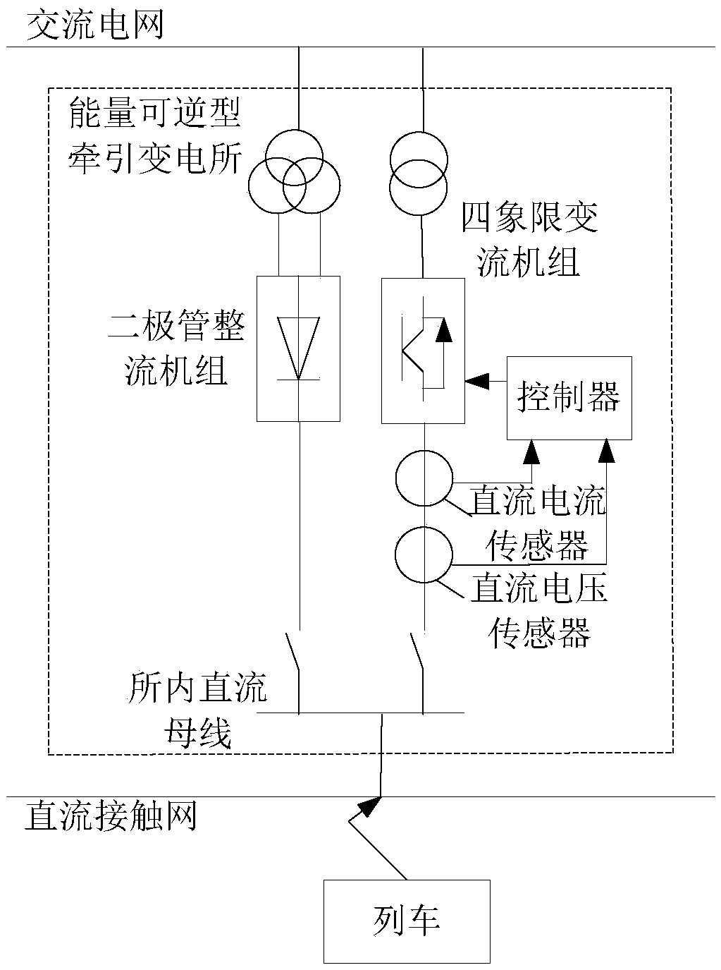
[0051] Usually, in the existing urban rail transit traction track system, regenerative braking energy will be generated when the train enters the station for braking, and the energy will be consumed by the resistor, which will cause a waste of resources. In order to reasonably and fully utilize the regenerative braking energy of trains, an energy reversible traction substation can be used in this embodiment, by controlling the DC given voltage of the four-quadrant converter unit in the energy reversible traction substation The value is changed in real time, so that the regenerative braking energy of the train can be jointly absorbed ...
PUM
 Abstract
Description
Claims
Application Information