
Flexible axle boxes and assembling method thereof, and bogie

A flexible shaft and bogie technology, applied in the field of bogies, can solve the problems of limited effect, increase train derailment, reduce the elastic suspension effect of axle boxes, etc., and achieve the effects of easy installation, restraining snaking motion, and increasing the critical speed of instability

Inactive Publication Date: 2018-07-03
CRRC YANGTZE CO LTD
View PDF8 Cites 1 Cited by
  • Summary
  • Abstract
  • Description
  • Claims
  • Application Information

AI Technical Summary

Problems solved by technology

Anyone with a little knowledge of vehicles knows that the critical running speed of vehicles in a straight line and the performance of vehicles passing through curves are a pair of contradictions, and it is often difficult to balance them in bogie design.
[0005] However, the existing axle box suspension devices generally adopt rigid positioning or one-level longitudinal rigidity positioning in the longitudinal direction. The rigid positioning between the bearing saddle and the side beam pedestal is dry friction, and the friction force increases linearly, which cannot adapt to high-speed operation. The wheel-rail lateral force is relatively large, which increases the risk of train derailment; some bogie schemes achieve elastic positioning, but the number of accessories is large. Due to structural limitations, the installation method is cumbersome and the effect is limited. The performance requirements of the vehicle passing through the curve greatly reduce the effect of the elastic suspension of the axle box

Method used


Image

  • Flexible axle boxes and assembling method thereof, and bogie
  • Flexible axle boxes and assembling method thereof, and bogie
  • Flexible axle boxes and assembling method thereof, and bogie

Examples


Embodiment Construction

[0034] The present invention will be further described in detail below in conjunction with the accompanying drawings and specific embodiments.

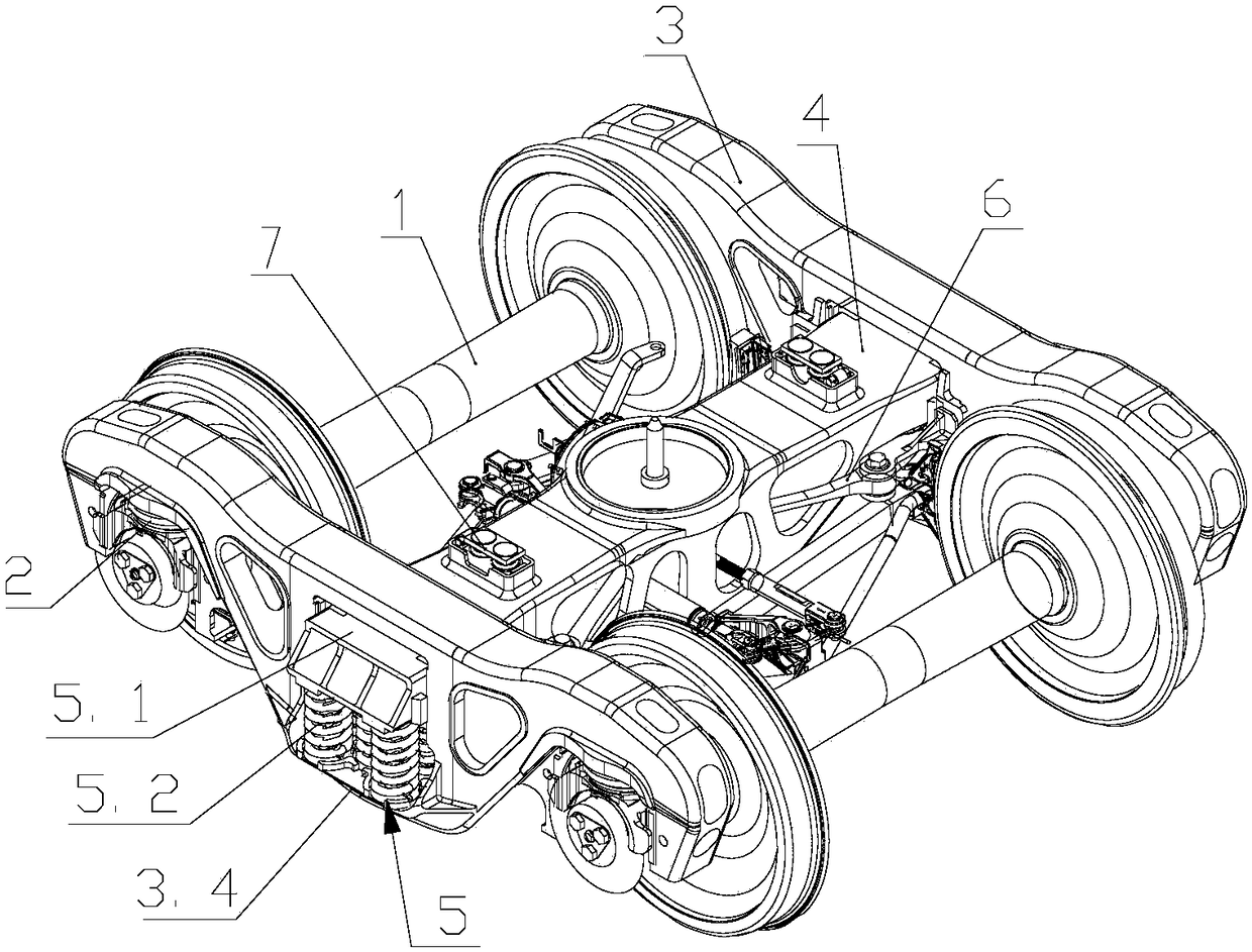
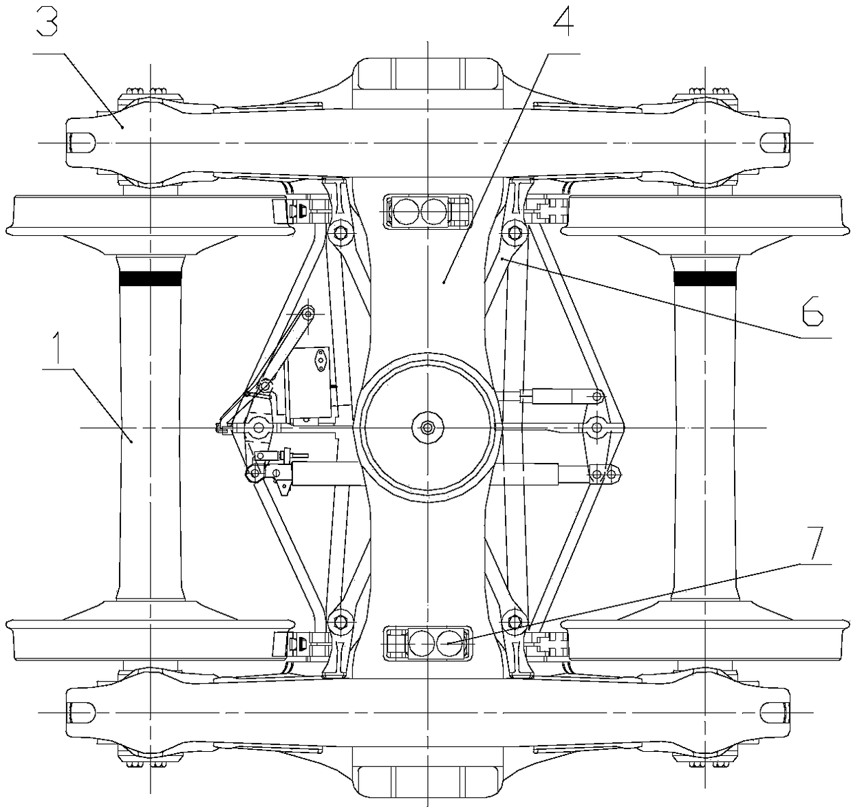
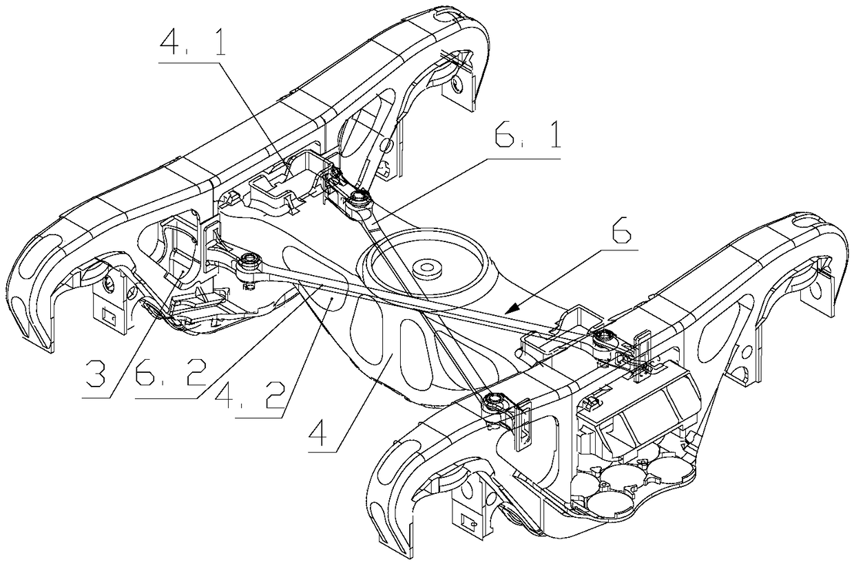
[0035] Such as Figure 1~3Shown in is a truck bogie with flexible axle box suspension, including two sets of wheels 1, and flexible axle boxes are arranged symmetrically on both sides of each wheel set 1, and the flexible axle box includes a flexible axle box body 2, two on the same side The flexible axle box body 2 is provided with a side beam component 3, and a cross beam component 4 arranged perpendicularly to the two side beam components 3 is arranged between the side beam components 3 on both sides; The middle part of the beam composition 3; the X-shaped connecting rod 6 is arranged under the cross-beam composition 4, and the axial ends of the X-shaped connecting rod 6 respectively pass through the webs on both sides of the cross-beam composition 4 and are fixedly connected with the side beam composition 3. The X-shaped connecti...


PUM


Abstract

The invention discloses flexible axle boxes and an assembling method thereof, and a bogie. The bogie comprises two sets of wheel pairs; the flexible axle boxes are symmetrically arranged on the two sides of each set of wheel pair; each flexible axle box comprises a flexible axle box body, side beam compositions are arranged on the two flexible axle box bodies on the same sides, and cross beam compositions perpendicular to the side beam compositions are arranged between the side beam compositions on the two sides; the two ends of the cross beam compositions are arranged in the middles of the side beam compositions through central damping suspension devices; X-shaped connecting rods are arranged below the cross beam compositions; and the two axial ends of the X-shaped connecting rods penetrate through webs on the two sides of the cross beam compositions correspondingly to be fixedly connected with the side beam compositions. According to the flexible axle boxes and the assembling methodthereof, and the bogie, the X-shaped connecting rods are arranged below the cross beam compositions, the two axial ends of the X-shaped connecting rods penetrate through webs on the two sides of the cross beam compositions correspondingly to be fixedly connected with the side beam compositions, and in the running process of a vehicle, the X-shaped connecting rods can effectively control mutual movement of the two side beam compositions on the left and the right, thus the purpose of inhibiting hunting movement of the bogie is achieved, and the instability critical speed of hunting movement is increased.

Description

technical field [0001] The invention relates to the technical field of bogies, in particular to a flexible axle box, an assembly method thereof, and a bogie. Background technique [0002] A railway vehicle is a vehicle that runs on a specially designed track. The railway vehicle bogie supports the weight of the entire cargo and the weight of the car body itself, runs along the specially designed track, and guides itself without controlling the direction. The bogie is an important part of a railway vehicle. Most railway freight car bogies are mainly three-piece structure including two side beams and a cross beam. The advantages of the three-piece bogie are simple structure, good wheel load uniformity, and low manufacturing and maintenance costs. However, because the device connection between the wheel set and the side beam is too loose or too tight, it is not conducive to the positioning of the wheel set, which is easy to cause the instability of the wheel set, and because ...

Claims


Application Information

Patent Timeline
Patent Type & Authority Applications(China)
IPC IPC(8): B61F5/26B61F5/14
CPCB61F5/26B61F5/14
Inventor 严志雄刘凤伟姜瑞金徐勇武慧平李华宴宋帆
Owner CRRC YANGTZE CO LTD
Learn More