Control method and control system for permanent magnet synchronous motor using large moment of inertia

A permanent magnet synchronous motor, control system technology, applied in vector control system, motor generator control, control system and other directions, can solve the problems of motor current oscillation, slow speed response, DC voltage increase, etc., to improve accuracy and speed performance, speed up dynamic response, and prevent DC overvoltage

Pending Publication Date: 2018-07-03
RES INST OF PHYSICAL & CHEM ENG OF NUCLEAR IND
View PDF4 Cites 8 Cited by
  • Summary
  • Abstract
  • Description
  • Claims
  • Application Information

AI Technical Summary

Problems solved by technology

Since the flywheel is a load with a large moment of inertia, the following problems exist in the process of using a permanent magnet synchronous motor to drive the flywheel: If the power of the motor control system is large, with a large moment of inertia and high-speed motor, once a fault occurs, even if the input of the motor control system is disconnected Open, the inverter stops running, because the output switch is not disconnected, and the motor with large moment of inertia runs at high speed, causing the back electromotive force of the motor to "fed back" to the DC side of the diode rectifier, resulting in an increase in DC voltage, and even breakdown of the motor control system SCR module
[0003] At the same time, when the speed of the flywheel changes, a large inertia torque will be generated, which will cause the motor current to oscillate during the control process, increase the tracking error, and slow the speed response, etc., resulting in a decrease in the performance of the motor control system.

Method used


Image

  • Control method and control system for permanent magnet synchronous motor using large moment of inertia
  • Control method and control system for permanent magnet synchronous motor using large moment of inertia
  • Control method and control system for permanent magnet synchronous motor using large moment of inertia

Examples


Embodiment 1

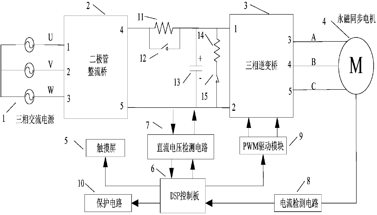
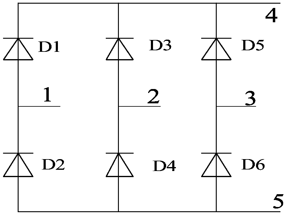
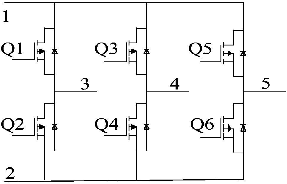
[0059] A control system for a permanent magnet synchronous motor with a large moment of inertia, including a rectifier bridge 2 whose input end is connected to the UVW three phases of the three-phase alternating current 1, and an output end ABC three-phase and surface-mounted permanent magnet synchronous motor 4 Correspondingly connected three-phase inverter bridge 3, and PWM drive module 9 and DSP control board 6, and the DC voltage detection circuit 7 used to detect the output voltage of the rectifier bridge electrically connected to the control board, in order to detect the permanent magnet synchronous motor The current detection circuit 8 and the protection circuit 10 of the stator current, the output of the DC voltage detection circuit and the current detection circuit are input to the protection circuit 10, the positive output of the rectifier bridge is connected in series with a charging resistor 11 and a DC contactor 12, The charging resistor 11, the other end of the DC...

Embodiment 2

[0070] The DC voltage detection circuit 7 of the present invention is used to collect the output voltage of the rectifier, and it includes positive and negative input terminals and the first operational amplifier 16 of the voltage acquisition terminal, and the output of the first operational amplifier 16 is adjusted by the signal after the resistor R5 The unit is then connected to the signal processing module, and at the same time, the output of the first operational amplifier is connected to the input terminal through a resistor R4, and a capacitor C2 is connected in parallel to the resistor R4. At the same time, the positive input terminal of the first operational amplifier is grounded after passing through the capacitor C1, and meanwhile, a resistor R3 is also provided in parallel with the capacitor C1.

[0071] The current detection circuit is used to collect the stator current of the motor, and it includes a sensor arranged on the stator. The positive pole and the negative...

Embodiment 3

[0079] The object of the present invention is a surface-mounted permanent magnet synchronous motor, and its direct axis and quadrature axis inductance are equal, so the basic equation of the motor under the d-q rotating coordinate system obtained through clarke and park transformation is:

[0080]

[0081]

[0082]

[0083] where L d , L q ---- Motor direct axis inductance, quadrature axis inductance;

[0084] u d , u q ----Motor direct axis voltage, quadrature axis voltage;

[0085] ω, ω m ---- Motor electrical angular velocity, mechanical angular velocity;

[0086] T e ,T l ---- Motor electromagnetic torque, load torque;

[0087] ψ f ----Excitation flux linkage of rotor permanent magnet poles;

[0088] R s ----motor stator resistance;

[0089] J----moment of inertia of the motor;

[0090] B m ----Motor friction coefficient.

[0091] Surface-mounted permanent magnet synchronous motors usually use i d = 0 vector control method, the vector control metho...


PUM


Abstract

The invention discloses a control method and a control system for a permanent magnet synchronous motor using a large moment of inertia. The control method comprises the following steps: 1) calculatingthe actual rotational speed of the motor, and calculating the torque current and the excitation current of the motor; 2) comparing the actual rotational speed with a preset rotational speed to obtaina deviation value, and outputting a current reference value via a speed regulator; 3) according to the motor speed increase and deceleration states, executing corresponding inertia compensation strategies; 4) comparing a torque current with the reference value of the torque current adjustment to obtain a comparison value, and then obtaining the output values of the AC and DC voltages via a current regulator; 5) obtaining the reference values of the AC and DC voltages; and 6) performing a space vector algorithm based on the reference values of the AC and DC voltages to obtain a PWM drive signal, and controlling the operation of a three-phase inverter bridge drive motor. Based on the double-loop vector control of the rotational speed current, the voltage feedforward decoupling and the moment of inertia feedforward control are designed to compensate the motor current in real time, which accelerates the dynamic response to the large moment of inertia load and improves the accuracy and rapidity of permanent magnet synchronous motor control system.

Description

technical field [0001] The invention belongs to the technical field of AC permanent magnet synchronous motor control, and in particular relates to a control method and a control system of a permanent magnet synchronous motor applying a large moment of inertia. Background technique [0002] AC permanent magnet synchronous motor has the advantages of high power density, excellent regulation performance, and good maintainability, and can work in two modes of driving and power generation. Therefore, it is generally used as a flywheel drive motor in flywheel energy storage devices. Since the flywheel is a load with a large moment of inertia, the following problems exist in the process of using a permanent magnet synchronous motor to drive the flywheel: If the power of the motor control system is large, with a large moment of inertia and high-speed motor, once a fault occurs, even if the input of the motor control system is disconnected Open, the inverter stops running, because th...

Claims


Application Information

Patent Timeline
Patent Type & Authority Applications(China)
IPC IPC(8): H02P21/22H02P21/36
CPCH02P21/22H02P21/36
Inventor 魏振赵武玲高亚男彭树文任祥正姚广岳金磊赵楠张楠
Owner RES INST OF PHYSICAL & CHEM ENG OF NUCLEAR IND
Why Eureka
Try Eureka