
Sanitary eight-valve beverage dispenser

A beverage machine and hygienic technology, applied in beverage preparation devices, home appliances, applications, etc., can solve problems such as increased costs, harmful to human health, and easy to be contaminated by bacteria, and achieve the effects of improving work efficiency, convenient operation, and simple structure

Inactive Publication Date: 2018-07-06
梧州市中盟贸易有限公司
View PDF0 Cites 0 Cited by
  • Summary
  • Abstract
  • Description
  • Claims
  • Application Information

AI Technical Summary

Problems solved by technology

[0002] Beverage machine is a small machine that many catering businesses will choose to sell beverages such as Coke, Sprite, and soy milk in the store. Currently, beverage machines on the market generally have three valves and four valves, and many businesses sell more than four types of beverages. It is necessary to purchase more than two beverage machines, which increases the cost, and the outlet of the traditional beverage machine is exposed for a long time, which is easy to be polluted and breeds a large number of bacteria. The beverage flowing out of the polluted outlet can be harmful to human health.

Method used


Image

  • Sanitary eight-valve beverage dispenser
  • Sanitary eight-valve beverage dispenser
  • Sanitary eight-valve beverage dispenser

Examples


Embodiment Construction

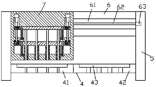
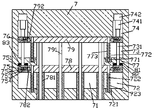
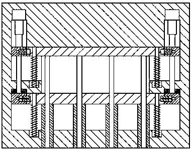
[0025] Such as Figure 1-Figure 8 As shown, a sanitary eight-valve beverage machine of the present invention includes a body and a beverage dispensing device 7. The beverage dispensing device 7 is provided with a mounting cavity 71, and the left and right sides of the mounting cavity 71 are correspondingly arranged from top to bottom. There are a first sliding groove 73, a partition plate 77, and a second sliding groove 72. Above the mounting cavity 71 is provided a first sliding rod 79 extending left and right, and the first sliding rod 79 extends left and right at the tail. They extend into the first sliding grooves 73 on the left and right sides and are connected in sliding cooperation. Below the placement cavity 71, there are second sliding rods 78 extending left and right. The extension tails respectively extend into the second sliding grooves 72 on the left and right sides and are connected in sliding cooperation. The bottom of the second sliding rod 78 is provided with f...


PUM


Abstract

The invention discloses a sanitary eight-valve beverage dispenser. The dispenser includes a dispenser body and a beverage discharging device; a mounting cavity is formed in the beverage discharging device, the left and right sides of the mounting cavity are correspondingly provided with a first sliding conveying groove, a clapboard and a second sliding conveying groove from top to bottom, a firstsliding conveying rod extending to the left and right sides is arranged above the mounting cavity, and the tail parts, extending to the left and right sides, of the first sliding conveying rod stretchinto the left and right sides of the first sliding conveying groove respectively and are cooperatively in sliding conveying connection with the left and right sides of the first sliding conveying groove; a second sliding conveying rod extending to the left and right sides is arranged below the mounting cavity, and the tail parts, extending to the left and right sides, of the second sliding conveying rod stretch into the left and right sides of the second sliding conveying groove respectively and are cooperatively in sliding conveying connection with the left and right sides of the second sliding conveying groove; four groups of outer beverage pipes extending downwards and penetrating through the bottom of the beverage discharging device are arranged on the bottom of the second sliding conveying rod, and each outer beverage pipe is internally and cooperatively in sliding conveying connection with an inner beverage pipe extending vertically. The beverage dispenser has the advantages ofbeing simple in structure, reasonable in design, convenient to operate, capable of achieving automatic control over switchable discharging of beverages through two groups of four valves and improvingthe work efficiency, and low in manufacturing cost and maintenance cost.

Description

Technical field [0001] The invention relates to the technical field of beverage machines, in particular to a sanitary eight-valve beverage machine. Background technique [0002] Beverage machine is a small machine that many catering businesses will choose to equip in the store for selling cola, sprite, soy milk and other beverages. At present, beverage machines on the market generally have three valves or four valves. Many businesses sell more than four varieties of beverages. At times, it is necessary to purchase more than two beverage machines, which increases the cost. Moreover, the outlet of the traditional beverage machine is exposed for a long time, which is easy to be polluted and breed a large number of bacteria. The beverage flowing out through the contaminated outlet can be harmful to human health. Summary of the invention [0003] The technical problem to be solved by the present invention is to provide a sanitary eight-valve beverage machine, which can solve the above-...

Claims


Application Information

Patent Timeline
Patent Type & Authority Applications(China)
IPC IPC(8): A47J31/00A47J31/46A47J31/44
CPCA47J31/00A47J31/4403A47J31/46
Inventor 王海球
Owner 梧州市中盟贸易有限公司
Learn More