A cross-flow stirring paddle

A stirring paddle and flow-through technology, which is applied in the field of stirring paddles, can solve problems such as low stirring efficiency, and achieve the effects of high stirring efficiency, improving mixing effect and shortening mixing time.

Active Publication Date: 2020-12-25
INST OF PROCESS ENG CHINESE ACAD OF SCI
View PDF9 Cites 0 Cited by
  • Summary
  • Abstract
  • Description
  • Claims
  • Application Information

AI Technical Summary

Problems solved by technology

[0005] The purpose of the present invention is to provide a through-flow stirring paddle to solve the problem of low stirring efficiency in existing stirring equipment for enhanced chaotic mixing

Method used


Image

  • A cross-flow stirring paddle
  • A cross-flow stirring paddle
  • A cross-flow stirring paddle

Examples


Embodiment 1

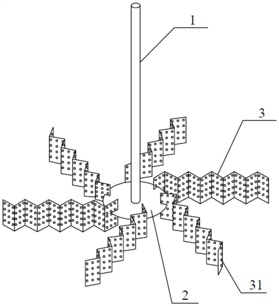
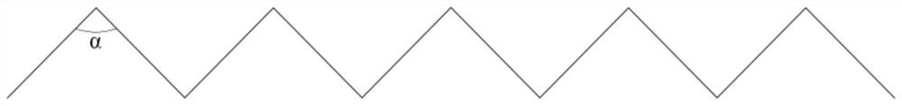
[0033] The stirred tank (not shown in the figure) reactor has a diameter of 240 mm and a height of 300 mm. Four baffles are installed away from the wall, and the baffles are 300 mm high and 20 mm wide. The top view of the through-flow paddle blade 3 is a broken line (ie figure 2 ), the angle α between two adjacent broken lines is 45°, the diameter of the through-flow hole 31 is 5 mm, and the center-to-center distance between two adjacent through-flow holes 31 is 10 mm. The paddle diameter of the paddle 3 is 80 mm, the paddle height is 24 mm, the number of blades of the paddle 3 is 6, and the height of the paddle 3 from the bottom is 80 mm.

[0034] Figure 5 It is a structural schematic diagram of the through-flow stirring paddle in the prior art, and its difference from the through-flow stirring paddle provided by the present invention is that the shape of the paddle 3 in the present invention is a wave-shaped structure, while the through-flow stirring paddle in the prior a...

Embodiment 2

[0040] Other conditions are the same as in Example 1, except that the diameter of the through-flow hole 31 is 6mm. The results of the comparative experiment are shown in Table 2.

[0041] Table 2 Performance comparison between the existing through-flow propeller and the high-efficiency through-flow propeller of the present invention

[0042]

[0043] It can be seen from the experimental results in Table 2 that at the same stirring speed, the mixing time of the through-flow stirring blade of the present invention is shortened by 12.75% compared with the existing through-flow stirring blade.

Embodiment 3

[0045] Other conditions are the same as in Example 1, except that the shape of the through-flow stirring paddle 3 is arc-shaped, and the results of the comparative experiment are shown in Table 3.

[0046] Table 3 Performance comparison between the existing through-flow paddle and the high-efficiency through-flow paddle of the present invention

[0047]

[0048] It can be seen from the experimental results in Table 3 that at the same stirring speed, the mixing time of the through-flow stirring blade of the present invention is shortened by 11.82% compared with the existing through-flow stirring blade.


PUM


Abstract

The invention belongs to the technical field of stirring paddles, and discloses a through-flow stirring paddle. The through-flow stirring paddle includes a stirring shaft, a disc and a paddle, the center of the disc is sleeved on the stirring shaft, the paddle is arranged on the disc along the circumferential direction, and the surface of the paddle is provided with a through-flow hole, and the surface of the paddle is It is a wavy structure. During the rotation of the high-efficiency through-flow stirring paddle of the present invention, after the fluid passes through the through-flow hole, many high-speed jets will be formed behind the blades of the wave-shaped structure, and impact flows will also be formed, which destroys the periodic motion of the fluid in the mixing isolation area. Therefore, the velocity gradient of the fluid in the stirring tank is increased, the mixing effect of the materials is improved, the mixing time of the materials is shortened, and the stirring efficiency is higher than that of the existing stirring equipment.

Description

technical field [0001] The invention relates to the technical field of stirring paddles, in particular to a through-flow stirring paddle. Background technique [0002] The paddle is the core component of the agitator, and its configuration (the paddle itself and the combination of multiple paddles) and operation (speed and installation position, etc.) are important factors affecting the performance of the agitator. At present, according to the classification of the fluid flow state in the agitator, the agitating paddles can be divided into axial paddles, radial paddles and mixing paddles, and each type of paddle includes many paddle types with different structures. When selecting the type of stirring impeller, it is necessary to comprehensively consider the properties of the stirring medium (such as viscosity, density and corrosiveness, etc.), the characteristics of the reaction process (such as intermittent or continuous, endothermic or exothermic), stirring effect and stir...

Claims


Application Information

Patent Timeline
Patent Type & Authority Patents(China)
IPC IPC(8): B01F7/00
CPCB01F27/0722B01F27/1123B01F27/074B01F27/11251
Inventor 杨超张庆华毛在砂李向阳程景才冯鑫段晓霞
Owner INST OF PROCESS ENG CHINESE ACAD OF SCI
Why Eureka
Try Eureka