
Production method of die-cutting foam rubber without knife marks

A production method and foam glue technology, applied in metal processing and other directions, can solve the problems of difficult die-cutting of foam tape, overflowing glue, easy deformation of products, etc., so as to avoid the reverse release and delamination of the colloid, and reduce the phenomenon of glue overflowing. , the effect of reducing the use of auxiliary materials

Active Publication Date: 2019-07-23
成都冠佳科技有限公司
View PDF12 Cites 0 Cited by
  • Summary
  • Abstract
  • Description
  • Claims
  • Application Information

AI Technical Summary

Problems solved by technology

[0002] With the development of the TFT-LCD liquid crystal panel industry, the application of foam glue in LCD is very mature, but the application in OLED flexible products has yet to be developed. The use of foam glue will be more extensive, and foam glue has unique properties. , for the curved surface, the matching of the concave-convex surface is quite strict, and the application has a certain thickness to play a role in shading. These functions will be better applied in OLED. With the development of the optoelectronic industry, the technical requirements of the die-cutting industry The die-cutting of foam tape is becoming more and more difficult, especially for products with thick and small materials, the error is plus or minus 0.1mm, for the thickness of foam tape is within 1mm, and the width is within 2mm, the product Easy to deform, beveled edge, burr, knife mark, glue overflow

Method used


Image

  • Production method of die-cutting foam rubber without knife marks
  • Production method of die-cutting foam rubber without knife marks
  • Production method of die-cutting foam rubber without knife marks

Examples


Embodiment Construction

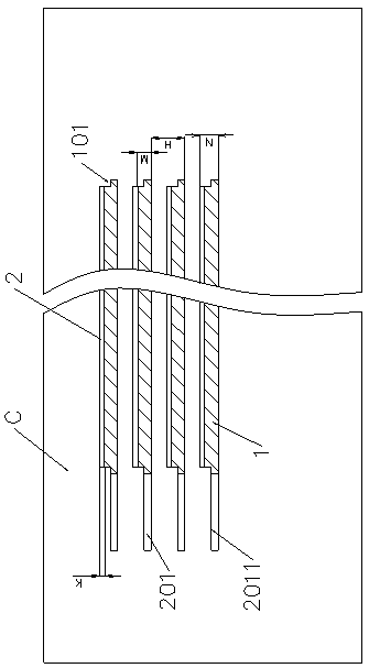
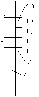
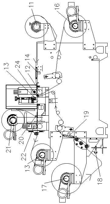
[0024] see figure 1 , 2 The foam glue shown is composed of tape units arranged at intervals on the base film C, and the tape unit includes a foam glue unit 1 and an isolation film unit 2 . The foam glue unit 1 has cutouts 101 on the upper left and right sides. The isolation film unit 2 is located between the base film C and the foam rubber unit 1 , and its left side part extends out of the foam rubber unit to form a tearing hand 201 , the upper edge 2011 of the tearing hand is flush with the bottom of the cutout 101 . The width of foam rubber unit 1 (at the widest point) M=1.75mm, the width of isolation membrane unit 2 (at the widest point) N=1.8mm, the lower edge of the foam rubber unit is flush with the lower edge of the isolation membrane unit, and the foam The upper edge of the glue unit is 0.05mm lower than the upper edge of the isolation membrane unit. The distance between tape units is H=4.4mm. The thickness of the foam glue unit is about 1 mm, and the thickness of ...


PUM


Abstract

The invention relates to a die cutting production method for a cut mark-free cotton adhesive tape . According to the method, a bottom film needs not to be replaced and waste is discharged conveniently, and the obtained cotton adhesive tape is free of burrs, cut marks and excessive glue. The production method comprises the following steps: feeding a laminated die obtained by laminating an isolatingfilm and the bottom film and the cotton adhesive tape without body paper step by step into a clearance machine for die cutting, wherein the cotton adhesive tape and the laminating die are stepped once after die cutting every time; cutting the middle main body part of the cotton adhesive tape by a lower cross cutter line, and forming a cotton adhesive tape unit, the width of which is equal to thestepping distance of the cotton adhesive tape, in the vertical direction of the middle main body part of the cotton adhesive tape during stepping every time and adhering the cotton adhesive tape unitto the surface of the isolating film; starting to calculate the die cutting number of times and the stepping number of times from 0 after stepping some time, encircling the cutting line of the middlemain body part of the isolating film by an upper cross cutter line and a side cutter line during (N+1)th die cutting and the cutting line of the middle main body part of the isolating film during Nthdie cutting after stepping for N times to form an isolating film unit; and discharging waste in the periphery of the isolating film unit.

Description

technical field [0001] The invention relates to a die-cutting production method of foam glue, belonging to the technical field of die-cutting. Background technique [0002] With the development of the TFT-LCD liquid crystal panel industry, the application of foam glue in LCD is very mature, but the application in OLED flexible products has yet to be developed. The use of foam glue will be more extensive, and foam glue has unique properties. , for the curved surface, the matching of the concave-convex surface is quite strict, and the application has a certain thickness to play a role in shading. These functions will be better applied in OLED. With the development of the optoelectronic industry, the technical requirements of the die-cutting industry The die-cutting of foam tape is becoming more and more difficult, especially for products with thick and small materials, the error is plus or minus 0.1mm, for the thickness of foam tape is within 1mm, and the width is within 2mm, ...

Claims


Application Information

Patent Timeline
Patent Type & Authority Patents(China)
IPC IPC(8): B26F1/38B26F1/44
CPCB26F1/38B26F1/44
Inventor 康书文王立林周剑波
Owner 成都冠佳科技有限公司
Learn More