Height-adjustable automatic plug-in new energy vehicle charging pile

A new energy vehicle, automatic plug-in technology, applied in electric vehicle charging technology, electric vehicles, charging stations, etc., can solve problems such as human body electric shock, and achieve the effect of ensuring stability and stable lifting

Inactive Publication Date: 2018-07-06
郑州恒之博新能源科技有限公司
View PDF1 Cites 4 Cited by
  • Summary
  • Abstract
  • Description
  • Claims
  • Application Information

AI Technical Summary

Problems solved by technology

[0006] The invention overcomes the deficiencies of the prior art, provides a new energy vehicle charging pile whose height is conveniently adjusted for automatic plugging and unplugging, and solves the problem that the existing new energy vehicles need to hold the gun body to charge and cause electric shock to the human body

Method used


Image

  • Height-adjustable automatic plug-in new energy vehicle charging pile
  • Height-adjustable automatic plug-in new energy vehicle charging pile

Examples


Embodiment 1

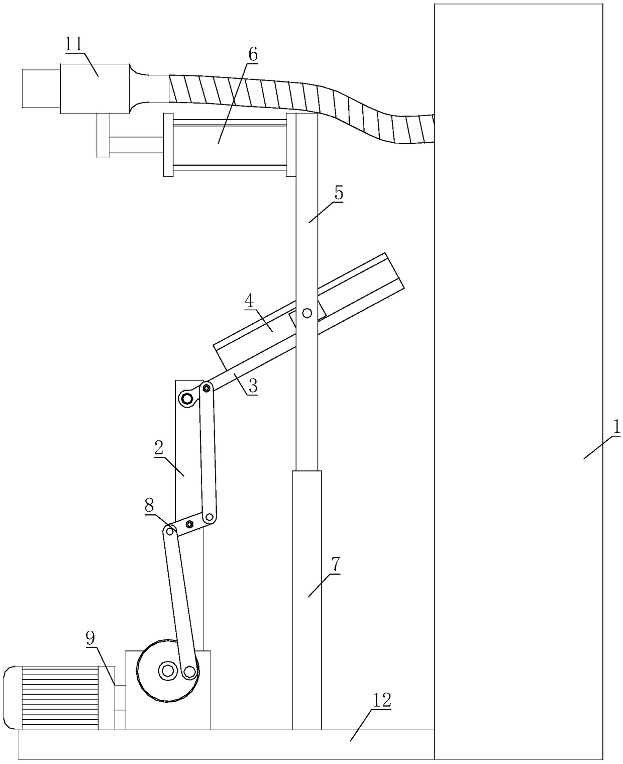
[0023] The height-adjustable automatic plug-in new energy vehicle charging pile includes a charging pile main body 1, and a charging plug 11 is connected to the charging pile main body 1; a mounting plate 12 is connected to the charging pile main body 1, and the mounting plate 12 is installed Mounting rod 2, the top of the mounting rod 2 is hinged with a rotating rod 3, the other end of the rotating rod 3 is fixed with a sliding mechanism 4, the sliding mechanism 4 is hinged with a lifting rod 5, the upper end of the lifting rod 5 is connected with a cylinder 6 The piston rod is fixed to the charging plug 11; a sleeve 7 is fixed on the mounting plate 12, and the other end of the lifting rod 5 is sleeved in the sleeve 7; the mounting rod 2 is hinged with a transmission mechanism 8, one end of the transmission mechanism 8 and a rotating rod The middle part of 3 is hinged, and the other end of the transmission mechanism 8 is hinged with a driving mechanism 9 for driving the transmi...

Embodiment 2

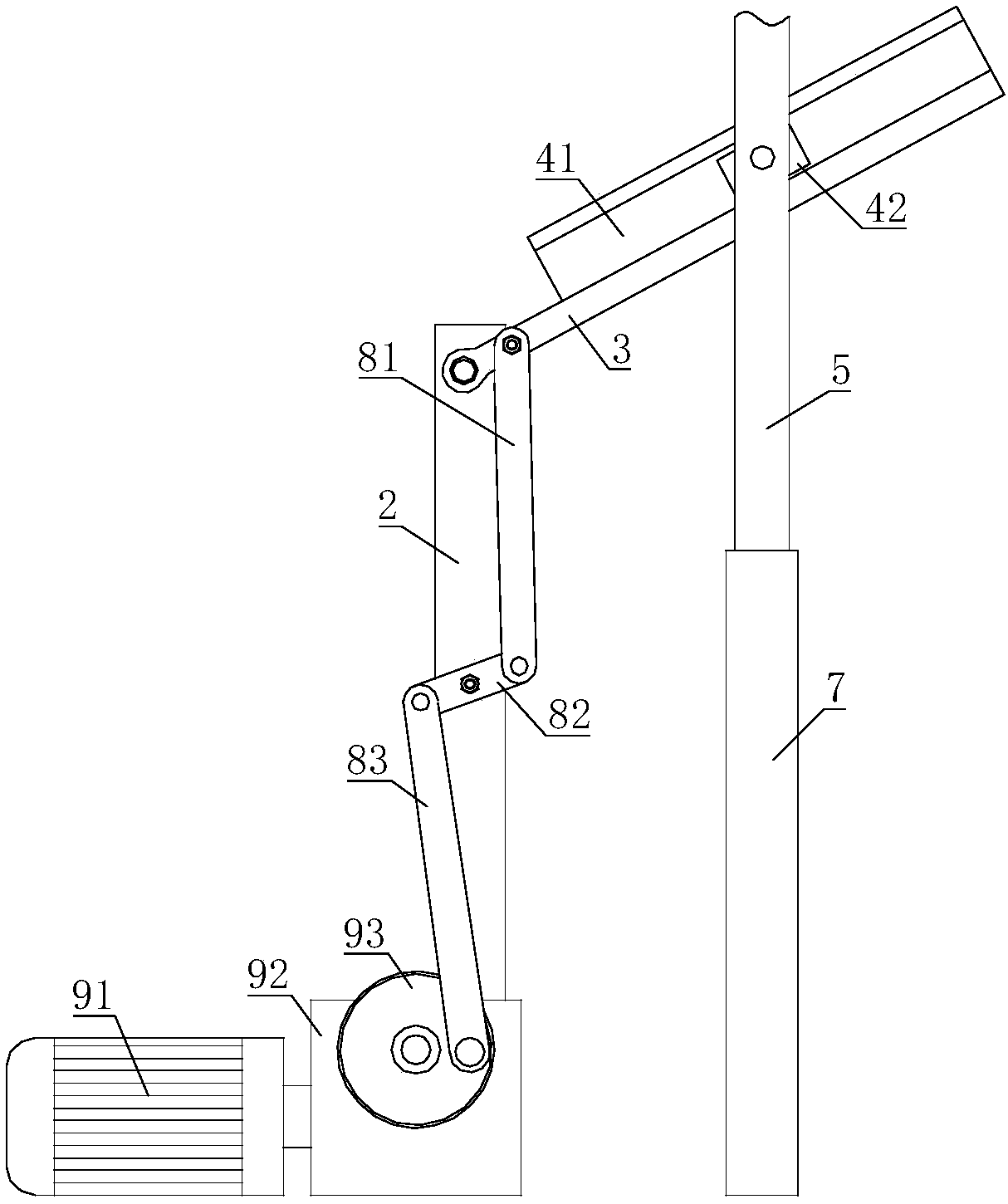
[0026] On the basis of the first embodiment, the transmission mechanism 8 includes a first link 81, one end of the first link 81 is hinged with the middle of the rotating rod 3, and the other end of the first link 81 is hinged with a rocker 82, The other end of the rod 82 is hinged with a second link 83, the middle of the rocker 82 is hinged on the mounting rod 2, and the other end of the second link 83 is hinged with the driving mechanism 9.

[0027] When the driving mechanism 9 pulls the second link 83 to move, the rocker 82 rotates accordingly, and the first link 81 moves under the drive of the rocker 82, so that the first link 81 can push the rotating rod 3 to tilt. According to needs, the driving mechanism 9 can change the transmission mechanism 8 to a certain shape by controlling the action time, so that the lifting rod 5, the air cylinder 6, and the charging plug 11 can be lifted accurately.

Embodiment 3

[0029] On the basis of the first or second embodiment, the driving mechanism 9 includes a motor 91, the output shaft of the motor 91 is connected with a reducer 92, the motor 91 and the reducer 92 are both mounted on the mounting plate 12, and the speed reducer 92 A turntable 93 is connected to the output shaft, and the transmission mechanism 8 is hinged with the edge of the turntable 93.

[0030] When the motor 91 drives the speed reducer 92 to move, the speed reducer 92 drives the turntable 93 to rotate, so that the transmission mechanism 8 drives the rotating rod 3 and the sliding mechanism 4 to tilt accordingly. When the motor 91 is stopped, the position of the lifting rod 5 cannot be changed by itself, which avoids the problem of the charging plug 11 falling down by itself.


PUM


Abstract

The invention relates to the field of charging piles for new energy vehicles, in particular to a height-adjustable automatic plug-in new energy vehicle charging pile. The charging pile comprises a charging pile body, and a charging plug is connected to the charging pile body; a mounting plate is connected to the charging pile body, a mounting rod is mounted on the mounting plate, a rotating rod ishinged to the top of the mounting rod, the other end of the rotating rod is fixed to a sliding mechanism, a lifting rod is hinged to the sliding mechanism, an air cylinder is connected to the upper end of the lifting rod, and a piston rod of the air cylinder is fixed to the charging plug; a sleeve is fixed on the mounting plate, and the other end of the lifting rod is sleeved with the sleeve; a transmission mechanism is hinged to the mounting rod, one end of the transmission mechanism is hinged to the middle of the rotating rod, the other end of the transmission mechanism is hinged to a driving mechanism for driving the transmission mechanism, and the driving mechanism is mounted on the mounting plate. The charging pile which is convenient in height adjustment and adopts an automatic plug-in mode is provided.

Description

Technical field [0001] The invention relates to the field of charging piles for new energy vehicles, in particular to a height-adjustable automatic pluggable new energy vehicle charging pile. Background technique [0002] The function of the charging pile is similar to the refueling machine in a gas station. It can be fixed on the ground or wall and installed in public buildings (public buildings, shopping malls, public parking lots, etc.) and residential community parking lots or charging stations. It can be based on different voltage levels. Charge various types of electric vehicles. The input end of the charging pile is directly connected to the AC grid, and the output end is equipped with a charging plug for charging electric vehicles. Charging piles generally provide two charging methods: conventional charging and fast charging. People can use a specific charging card to swipe the card on the human-computer interaction interface provided by the charging pile to perform corr...

Claims


Application Information

Patent Timeline
Patent Type & Authority Applications(China)
IPC IPC(8): B60L11/18H01R13/60
CPCB60L53/31H01R13/60Y02T10/70Y02T10/7072Y02T90/12
Inventor 曾皓
Owner 郑州恒之博新能源科技有限公司
Why Eureka
Try Eureka