Continuous pipe pasting device

A tube sticking and conveying device technology, applied in packaging, labeling machines, transportation and packaging, etc., can solve problems such as unusable cup shape, poor stability, and many operators, and achieve high fault tolerance, high-speed operation, and adaptability strong effect

Inactive Publication Date: 2018-07-06
广州市铭慧机械股份有限公司
View PDF9 Cites 3 Cited by
  • Summary
  • Abstract
  • Description
  • Claims
  • Application Information

AI Technical Summary

Problems solved by technology

Nowadays, the automatic tube sticking machine production line for cup-shaped outer packaging has slow speed, poor stability, many operators, and the tube sticking ...

Method used


Image

  • Continuous pipe pasting device
  • Continuous pipe pasting device
  • Continuous pipe pasting device

Examples


Embodiment

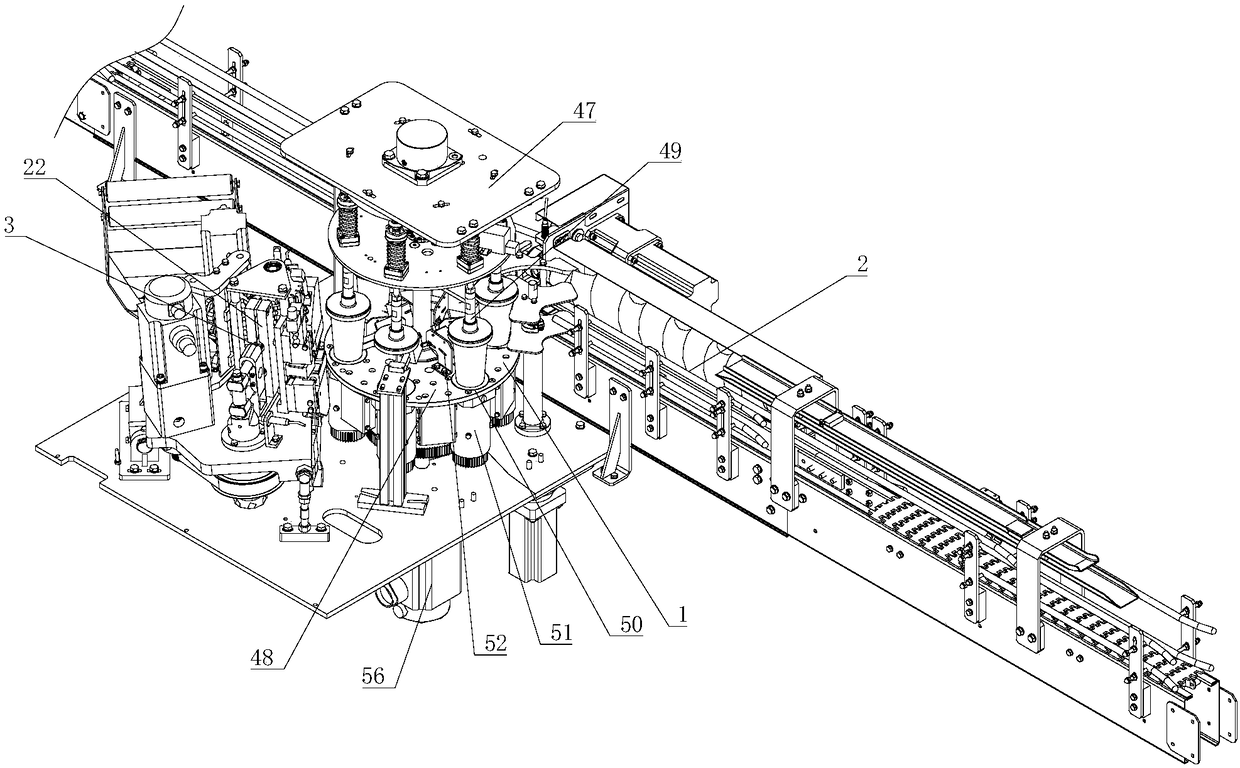
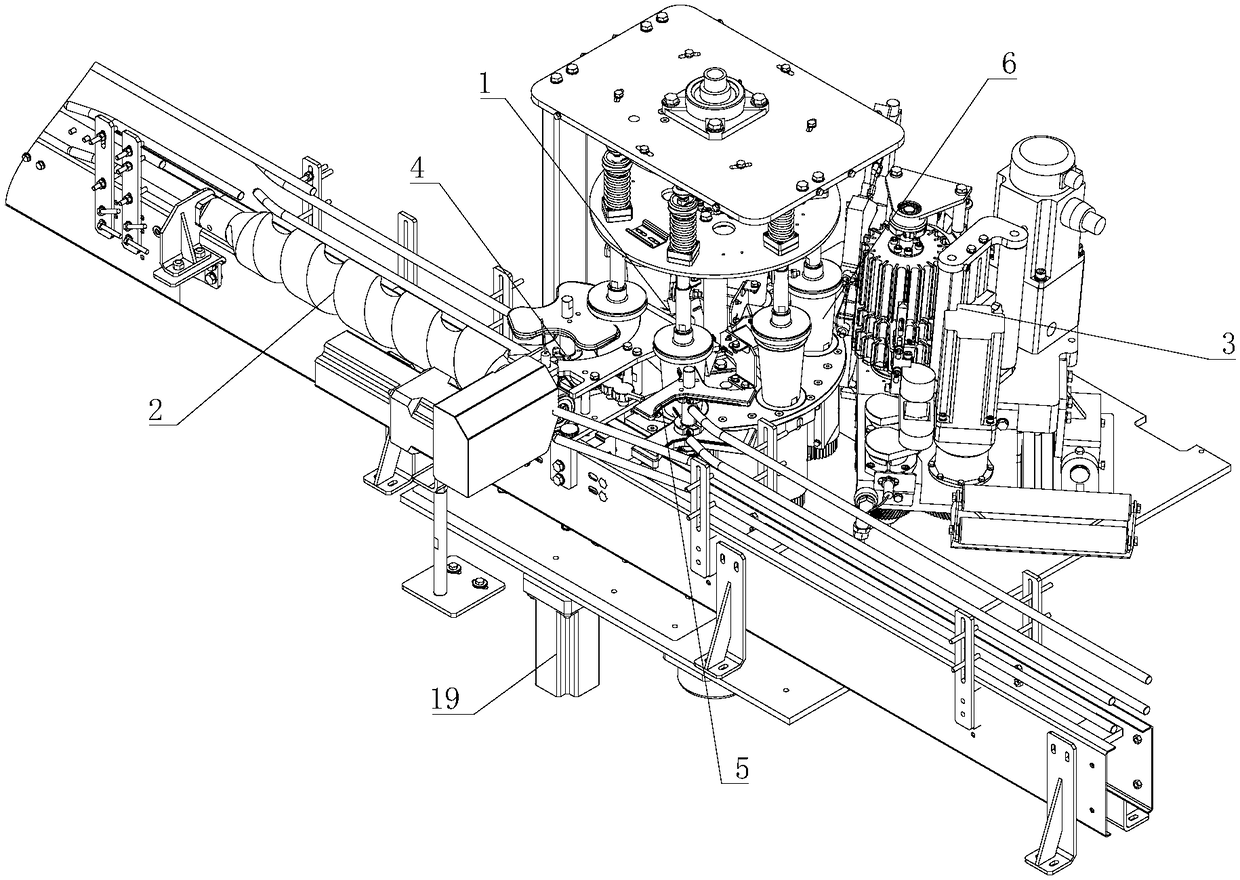
[0028] Such as figure 1 , figure 2As shown, a continuous tube sticking device includes a rotor cup device 1, a cup material conveying device 2, and a tube sticking device 3; the rotor cup device 1 is provided with an inlet 4, an outlet 5 and a plurality of surrounding To the set station 6, the station 6 revolves around the central axis, and the cup device 1 can drive the cup material positioned on the station 6 to perform autorotation and stop autorotation after turning to a specific position; The cup material conveying device 2 is arranged on one side of the feed port 4 and the discharge port 5 of the rotor device 1, and it is used to send the cup material to the station 6 of the rotor device 1 in sequence and The cup material after sticking the tube is sent out from the station 6; the tube sticking device 3 is arranged on the side of the rotor cup device 1 away from the feed port 4 and the discharge port 5, which is used to align the rotor cup device 1 After positioning, ...


PUM


Abstract

A continuous pipe pasting device comprises a cup rotating device, a cup material conveying device and a pipe pasting device body. The cup rotating device is provided with a feeding port, a dischargingport and a plurality of stations arranged in the circumferential direction. The stations conduct revolution around a center shaft. The cup rotating device can drive cup materials positioned on the stations to do the self-rotation movement, and the cup materials stop self-rotation after conducting self-rotation to the specific positions. The cup material conveying device is arranged on one side ofthe feeding port and the discharging port of the cup rotating device and is used for sequentially conveying the cup materials to the stations of the cup rotating device, and the cup materials obtained after pipe pasting are conveyed out of the stations. The pipe pasting device body is arranged on the side, deviating from the feeding port and the discharging port, of the cup rotating device and isused for conducting the pipe pasting procedure on the cup materials positioned through the cup rotating device. The continuous pipe pasting device has the beneficial effects that adaptability is high, the error-tolerant rate for products is high, and the continuous pipe pasting device can be applicable to different sizes of products only through simple modification.

Description

technical field [0001] The invention relates to the field of food packaging and processing equipment, in particular to a continuous tube sticking device. Background technique [0002] For a long time, with the development of the domestic packaging industry, the requirements for food packaging have become higher and higher, and the shapes of packaging have become more and more diverse. Nowadays, the automatic tube sticking machine production line for cup-shaped outer packaging has slow speed, poor stability, many operators, and the tube sticking equipment is suitable for square brick-shaped packaging, which cannot be used for cup-shaped packaging, and the positioning of the tube sticking position is not accurate. Contents of the invention [0003] The purpose of the present invention is to overcome the above-mentioned shortcomings of the prior art, and provide a continuous tube sticking device for continuous, stable and efficient tube sticking processing for cup-shaped oute...

Claims


Application Information

Patent Timeline
IPC IPC(8): B65C9/02B65C9/04B65C9/26B65C9/00
Inventor 罗朝炜
Owner 广州市铭慧机械股份有限公司
Why Eureka
Try Eureka