Single photon detector system and control method thereof

A single-photon detector and controller technology, applied in the field of quantum physics engineering applications, can solve problems such as being unsuitable for application development, prone to errors, and complicated operations, so as to shorten the detection dead time, improve the output code rate, and optimize performance. The effect of the indicator

Inactive Publication Date: 2018-07-06
STATE GRID CORP OF CHINA +1
View PDF6 Cites 6 Cited by
  • Summary
  • Abstract
  • Description
  • Claims
  • Application Information

AI Technical Summary

Problems solved by technology

Although this technical solution can achieve the effect of shortening the detection dead time, it is not suitable for application development due to the complicated operation and high cost to reduce the dead time by optimizing various parameters.

Method used


Image

  • Single photon detector system and control method thereof
  • Single photon detector system and control method thereof
  • Single photon detector system and control method thereof

Examples


Embodiment 1

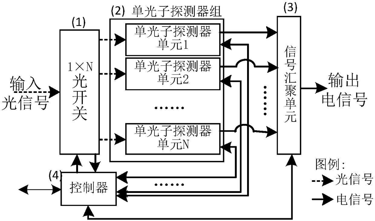
[0087] Image 6 Shows the structure diagram of the single-photon detector system in which the detection dead time is shortened to a quarter in embodiment 1 of the present invention, such as Image 6 As shown: the system may include: 1×4 optical switch 1, single photon detector group 2, signal convergence unit 3 and controller 4;

[0088] The 1×4 optical switch 1, the single-photon detector group 2 and the signal convergence unit 3 are connected in sequence;

[0089] The controller 4 is respectively connected to the 1×4 optical switch 1, the single-photon detector group 2 and the signal convergence unit 3;

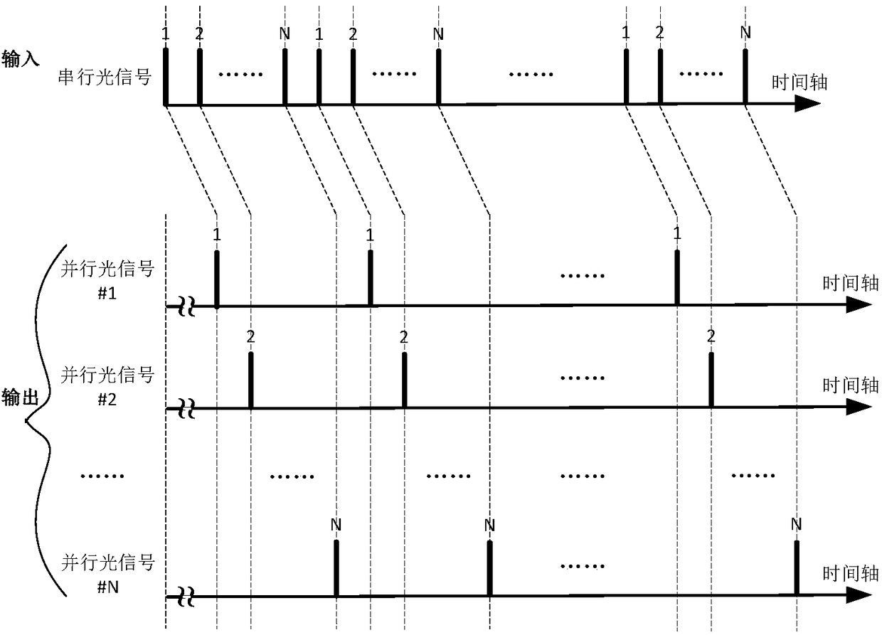
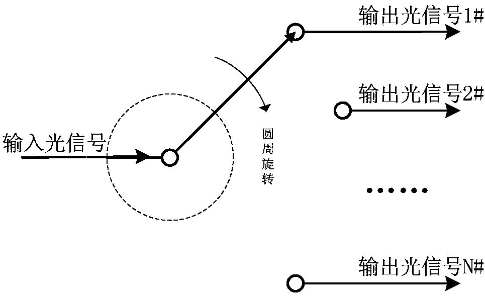
[0090] The 1×4 optical switch 1 is used to complete the serial / parallel conversion of optical signals; the single-photon detector group 2 is used to convert parallel optical signals into parallel electrical signals;

[0091] The signal convergence unit 3 is used to complete the parallel / serial conversion of electrical signals;

[0092] The controller 4 is used to control the executio...

Embodiment 2

[0114] Figure 8 Shows the structure diagram of the single-photon detector system with the detection dead time shortened to one sixteenth in embodiment 1 of the present invention, such as Figure 8 As shown: the system can include: 1×16 optical switch 1, single photon detector group 2, signal convergence unit 3 and controller 4;

[0115] The 1×16 optical switch 1, the single-photon detector group 2 and the signal convergence unit 3 are connected in sequence;

[0116] The controller 4 is respectively connected to the 1×16 optical switch 1, the single photon detector group 2 and the signal convergence unit 3;

[0117] The 1×16 optical switch 1 is used to complete serial / parallel conversion of optical signals; the single-photon detector group 2 is used to convert parallel optical signals into parallel electrical signals;

[0118] The signal convergence unit 3 is used to complete the parallel / serial conversion of electrical signals;

[0119] The controller 4 is used to control the execution...

Embodiment 3

[0141] Picture 9 Shows the system diagram of the single-photon detector with the detection dead time shortened to one-sixty-fourth in embodiment 1 of the present invention, such as Picture 9 As shown, the system may include: a 1×64 optical switch 1, a single photon detector group 2, a signal convergence unit 3, and a controller 4;

[0142] The 1×64 optical switch 1, the single-photon detector group 2 and the signal convergence unit 3 are connected in sequence;

[0143] The controller 4 is respectively connected with a 1×64 optical switch 1, a single photon detector group 2 and a signal convergence unit 3;

[0144] The 1×64 optical switch 1 is used to complete the serial / parallel conversion of optical signals; the single-photon detector group 2 is used to convert parallel optical signals into parallel electrical signals;

[0145] The signal convergence unit 3 is used to complete the parallel / serial conversion of electrical signals;

[0146] The controller 4 is used to control the execu...


PUM


Abstract

The invention relates to a single photon detector system and a control method thereof. The single photon detector system is composed of a 1*N optical switch, a single photon detector group, a signal convergence unit, and a controller connected with the 1*N optical switch, the single photon detector group, and the signal convergence unit. The 1*N optical switch transforms a serial optical pulse signal at a high bit rate at an input terminal into N-path parallel optical pulse signals at a low bit rate; N single photon detector units with the same performances work in parallel to transform N-pathparallel optical signals into N parallel electrical signals; and the signal convergence unit is used for realizing parallel-series transformation of the electrical signal and restoring outputting ofa single photon detection result. Therefore, the limitation problem of the dead time of the single photon detector is solved and thus the maximum counting rate of the single photon detector system isincreased; and the technical and economic limitation problem of the high-speed single photon detector is solved.

Description

Technical field [0001] The invention relates to the application field of quantum physics engineering, in particular to a single-photon detector system and a control method. Background technique [0002] Single photon detector / detection (SPD), as an optical signal measurement technology with extreme sensitivity, has an irreplaceable role in quantum information technology, physics, chemistry, biology, and astronomy, and has become an indispensable in the field of quantum information. The lack of core key technology; single-photon detectors are used to convert light signals into electrical signals based on single-photon detection. Since quantum information technology uses a single elementary particle to encode and manipulate information, it has extremely demanding performance for single-photon detectors. Requirements, such as detection efficiency, count rate, dead time, etc., far exceed the performance indicators that existing devices can achieve. Single-photon detectors need a cert...

Claims


Application Information

Patent Timeline
Patent Type & Authority Applications(China)
IPC IPC(8): G01J11/00
CPCG01J11/00
Inventor 苗浡瑞苗新
Owner STATE GRID CORP OF CHINA
Why Eureka
Try Eureka