Wind tunnel device for continuous high temperature sealing performance test

A high-temperature sealing and performance technology, used in measurement devices, liquid/vacuum measurement for liquid tightness, and testing of machinery/structural components, etc. Seal performance and other issues, to achieve good control accuracy and adjustment characteristics, heating and cooling rate blocks, temperature adjustment and stable effects

Active Publication Date: 2020-09-22
BEIJING UNIV OF CHEM TECH
View PDF19 Cites 0 Cited by
  • Summary
  • Abstract
  • Description
  • Claims
  • Application Information

AI Technical Summary

Problems solved by technology

In 2013, Harbin Institute of Technology invented a high-temperature structural sealing performance ground simulation test device and test method (CN103207054A), which also uses the gas heating device used in the arc jet control surface sealing test fixture device developed by NASA Green Research Center , the device uses a plug calorimeter to calibrate and test the heat flux state to determine the distance between the outlet of the heating device and the surface of the seal of the composite structure and the intake flow rate. Therefore, there is also the problem that the gas temperature and airflow pressure cannot be accurately controlled, and there is no precise design. A device to adjust the amount of compression. At the same time, because no heat insulation measures are taken in the sealed chamber behind the seal, the flame will heat the chamber and radiate heat into the sealed chamber through the inner wall surface, resulting in deviations in the final test temperature.
At the same time, the pressure difference between the front and rear of the seal is reflected by measuring the pressure of the pressure chamber connected to the test section. This can only measure the pressure of the seal when it is in use, and cannot test the seal under different conditions by accurately controlling the pressure before and after the seal. Performance at Differential Pressure

Method used


Image

  • Wind tunnel device for continuous high temperature sealing performance test
  • Wind tunnel device for continuous high temperature sealing performance test
  • Wind tunnel device for continuous high temperature sealing performance test

Examples


Embodiment

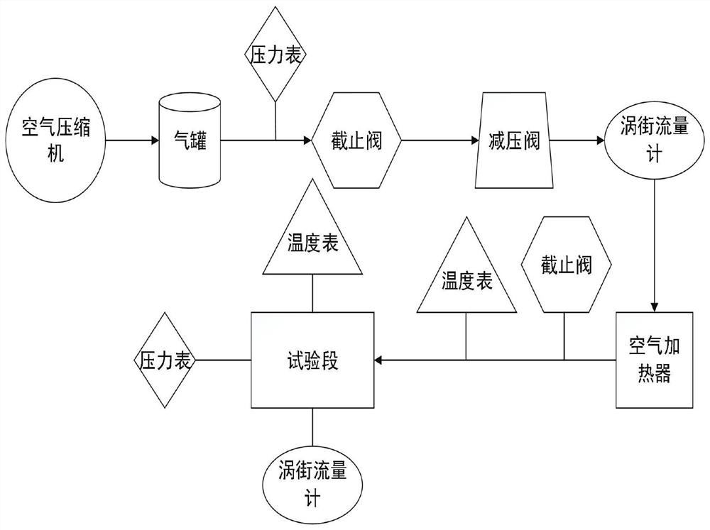
[0043] as attached figure 1 , the wind tunnel device for continuous high-temperature sealing performance testing includes a complete set of testing and testing systems, which can simulate thermal and airtight performance under various conditions. The installation process is as shown in the figure.

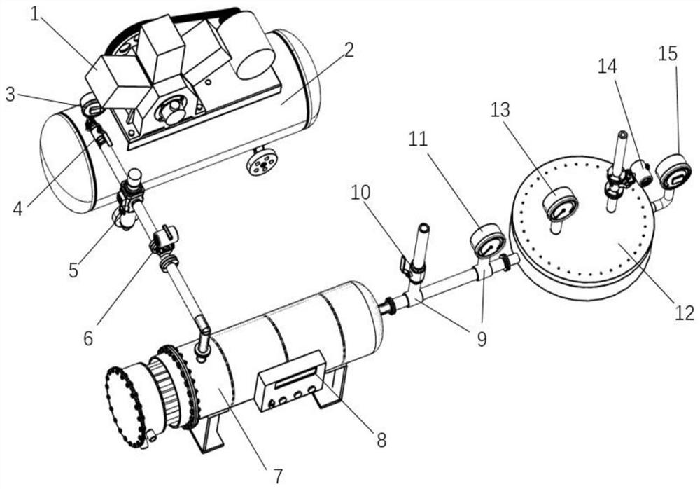
[0044] as attached figure 2 , the wind tunnel device for continuous high-temperature sealing performance testing includes an air compressor (1), a gas cylinder (2), a normal temperature pressure gauge (3), a stop valve a (4), a pressure reducing valve (5), and an air flow meter a(6), pipeline air heater (7), shut-off valve b(10), high temperature thermometer a(11), high temperature pressure gauge (15), test section (12), air flow meter b(14) and high temperature Thermometer b (13).

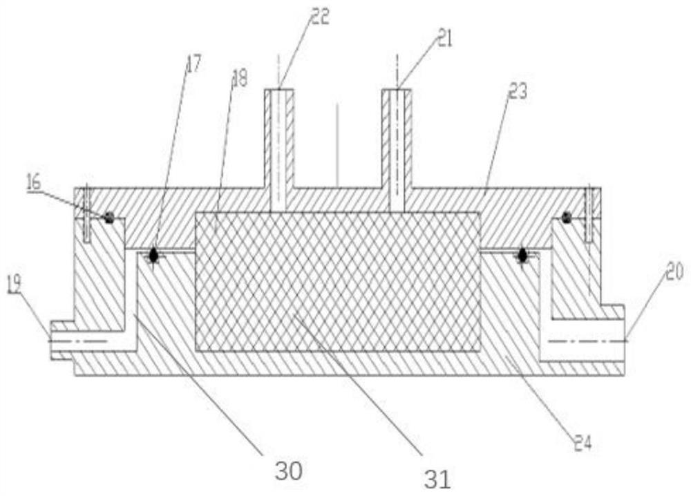
[0045] as attached image 3 , the test section includes a base (24), an air inlet (19), an upper cover (23), an air outlet (21), a seal (17), an adjusting gasket (16), an airgel (18), a high temper...


PUM


Abstract

The invention discloses a wind tunnel device for continuous high-temperature sealing performance testing. The wind tunnel device is composed of an air compressor, a gas cylinder, a normal-temperaturepressure gauge, a stop valve a, a reducing valve, an air flow meter a, a pipeline type air heater, a stop valve b, a high-temperature thermometer a, high-temperature pressure gauge, a test section, anair flow meter b, and a high-temperature thermometer b. The air compressor pressurizes air and stores the processed air in the gas cylinder; the reducing valve adjusts the pressure; heating is carried out by using the pipeline type air heater; with the test section, a testing piece is fixed in a specific trench of the test section, the distance between an upper cover plate of the test section anda pedestal is changed by replacing adjusting gaskets with different dimensions so as to change the compression amount of the testing piece; and with the high-temperature thermometer a, the high-temperature pressure gauge, the air flow meter b, and the high-temperature thermometer b arranged in front of and in rear of a sealing device, sealing and heat insulating parameters of the testing piece onthe conditions of different compression amounts, different pressure differences, and different temperatures are obtained.

Description

technical field [0001] The invention relates to a continuous high-temperature sealing performance test wind tunnel device, which is mainly used in the technical field of sealing performance experiments of various materials such as aviation sealing materials. Background technique [0002] High-temperature sealing plays a very important role in industrial production and is widely used in various high-temperature reaction furnaces and combustion chambers in the energy industry. High-temperature sealing is also widely used in the aerospace and aviation industries, and the sealing performance has a decisive impact on the performance of the aircraft. For example, the X-51A hypersonic test vehicle that was tested by the United States failed to reach the predetermined Mach number in the first flight test because of the seal leakage between the engine and the tail nozzle. Nowadays, with the rapid advancement of aerospace technology and the increasingly complex military evolution of ...

Claims


Application Information

Patent Timeline
Patent Type & Authority Patents(China)
IPC IPC(8): G01M3/02G01M9/02
CPCG01M3/02G01M9/02
Inventor 王维民巴全坤纳磊户东方
Owner BEIJING UNIV OF CHEM TECH
Why Eureka
Try Eureka