
Printed circuit board and terminal

A technology of printed circuit boards and grounding points, applied in the directions of printed circuit board sockets, printed circuits, printed circuits, etc., can solve the problem that the antenna radiation performance cannot be guaranteed, and achieve lower resonance frequency, reduced parasitic capacitance, and guaranteed radiation. performance effect

Active Publication Date: 2018-07-06
HUIZHOU TCL MOBILE COMM CO LTD
View PDF7 Cites 4 Cited by
  • Summary
  • Abstract
  • Description
  • Claims
  • Application Information

AI Technical Summary

Problems solved by technology

[0004] The invention provides a printed circuit board and a terminal to solve the technical problem in the prior art that the radiation performance of the antenna cannot be guaranteed while reducing the SAR of WiFi

Method used


Image

  • Printed circuit board and terminal
  • Printed circuit board and terminal
  • Printed circuit board and terminal

Examples


Embodiment Construction

[0027] The following will clearly and completely describe the technical solutions in the embodiments of the present invention with reference to the accompanying drawings in the embodiments of the present invention. Obviously, the described embodiments are only some, not all, embodiments of the present invention. Based on the embodiments of the present invention, all other embodiments obtained by persons of ordinary skill in the art without making creative efforts belong to the protection scope of the present invention.

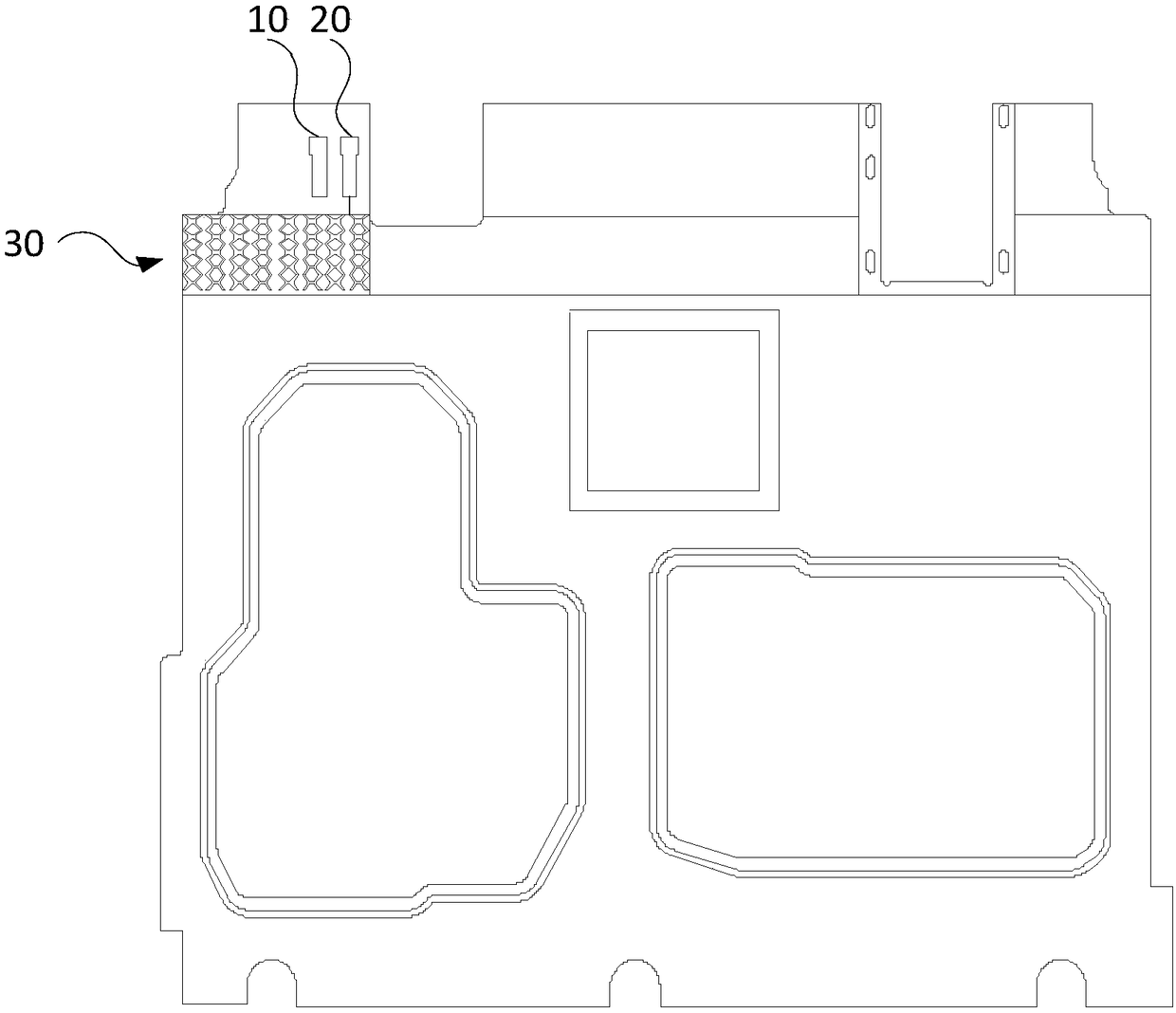
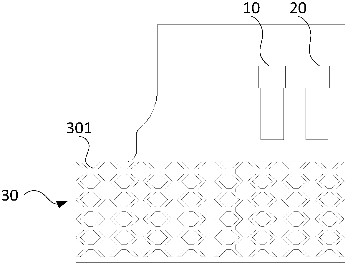
[0028] see figure 1 An embodiment of the printed circuit board of the present invention includes a feed point setting area 10, a ground point setting area 20 and a grounding area 30. The feed point setting area 10 is used to set an antenna feed point, and the antenna feed point is connected to a video chip (not shown in the figure) out) output; the ground point setting area 20 is adjacent to the feed point setting area 10, and is used to set the antenna ground...


PUM


Abstract

The invention discloses a printed circuit board and a terminal. The printed circuit board comprises a feed point setting region, a grounding point setting region and a grounding region; the feed pointsetting region is used for setting an antenna feed point; the grounding point setting region is adjacent to the feed point setting region and used for setting an antenna grounding point; and the grounding region is adjacent to and connected to the grounding point setting region and used as an antenna floor, wherein a radiation lowering structure is arranged in the grounding region. By setting theradiation lowering structure in the grounding region of the printed circuit board, the current flowing through circuit in the grounding region is prolonged, so that inductance between the grounding region and the antenna is increased, the stray capacitance is lowered, the resonant frequency of the antenna is lowered, the SAR of WiFi is lowered, and the radiation performance of the antenna is ensured.

Description

technical field [0001] The invention relates to the technical field of antennas, in particular to a printed circuit board and a terminal. Background technique [0002] In daily life, when users use terminals such as mobile phones, in addition to making calls and using data traffic to surf the Internet, radiation will also be generated when using WiFi (WIreless-Fidelity, wireless network). High, to reduce the WiFi radiation of the terminal, that is, the SAR (specific absorption rate, special absorption rate) of WiFi, which is beneficial to the health of the user. [0003] The inventors of this application have found in long-term research and development that the current technologies for reducing WiFi radiation mainly include reducing the conduction power, adding sensors, and changing the antenna structure. Both reducing the conduction power and changing the antenna structure will affect the radiation performance of WiFi, and adding sensors will It takes up more space, which ...

Claims


Application Information

Patent Timeline
Patent Type & Authority Applications(China)
IPC IPC(8): H01Q1/48H01Q17/00H01Q1/24
CPCH01Q1/24H01Q1/48H01Q17/00H01Q1/243H01Q1/526H05K1/0224H05K2201/09681H05K1/0243H05K7/1427H05K2201/10098
Inventor 陈磊刘莉云
Owner HUIZHOU TCL MOBILE COMM CO LTD
Learn More