Suction pile provided with suction device on pile side

A technology of suction device and suction pile, which is applied in the field of suction pile, can solve the problems of complex pile foundation structure, small friction coefficient, high water content, etc., and achieve the effect of increasing the scope of application of the project, increasing the total bearing capacity, and good stability

Active Publication Date: 2020-04-21
ZHEJIANG UNIV OF TECH
View PDF6 Cites 0 Cited by
  • Summary
  • Abstract
  • Description
  • Claims
  • Application Information

AI Technical Summary

Problems solved by technology

[0004] However, when the geological conditions are poor, such as saturated soft clay, its water content is high, its strength is low, and its friction coefficient is small, so the total resistance provided is often small, while the traditional method increases the end area or increases the pile length. The measure of pile foundation bearing capacity has the defects of low efficiency and high cost
At the same time, the traditional method of increasing the contact area at the end to increase the bearing capacity of the pile foundation makes the pile foundation structure more complicated and brings great inconvenience to the construction.

Method used


Image

  • Suction pile provided with suction device on pile side
  • Suction pile provided with suction device on pile side

Examples


Embodiment Construction

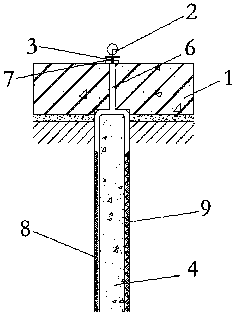
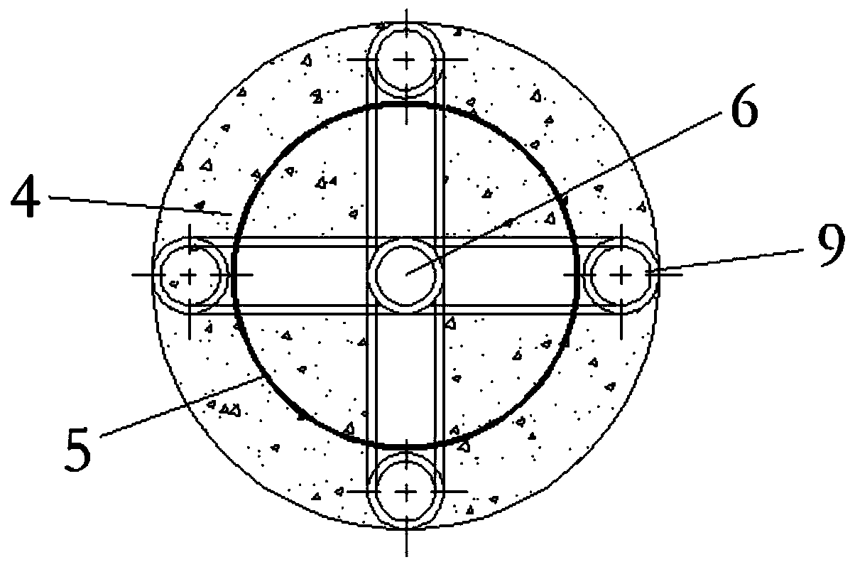
[0020] With reference to accompanying drawing, a kind of suction pile that is provided with suction device on pile side, comprises columnar pile body 4, and pile body 4 comprises reinforcement cage 5 and the concrete that pours along reinforcement cage 5; The bottom end of pile body 4 is sealed and embedded in In the soil body, the top of the pile body 4 extends vertically upwards and supports the cap 1; the pile body 4 is equipped with a suction force for increasing the effective stress of the soil around the pile (the soil around the pile refers to the soil around the pile body 4) device;

[0021] The suction device includes an upper air extraction pipe 6 and a lower air extraction pipe 9, and several lower air extraction pipes 9 are enclosed around the steel cage 5 and fixed on the steel cage 5, and the lower air extraction pipe 9 is uniform along the circumferential direction of the steel cage 5. Set at intervals; the lower air extraction pipe 9 extends from the top end fa...


PUM


Abstract

The invention discloses a force suction pile with a force suction device arranged on the pile side. The force suction device used for improving the effective stress of soil around the pile is arrangedon a pile body. Multiple lower gas suction piles are arranged around a reinforcement cage and are fixed to the reinforcement cage, and the lower gas suction piles are evenly arranged in the peripheral direction of the reinforcement cage at intervals. The lower gas suction piles extend to the end face of the bottom end of the pile body in the length direction of the pile body from the end face ofthe top end of the pile body. The outer wall faces of the lower gas suction pipes make contact with the soil body, and screen holes used for communicating the soil body and inner cavities of the lowergas suction pipes are evenly distributed in the outer wall faces of the lower gas suction pipes. Gas inlets in the bottom ends of upper gas suction pipes communicate with openings in the top ends ofthe lower gas suction pipes. Air outlets in the top ends of the upper gas suction pipes are located in the top face of a bearing table. The force suction pile further comprises vacuum valves located on the top face of the bearing table and used for being connected with a gas suction device, and pressure measuring meters which are used for monitoring the pressure in the inner cavities of the lowergas suction pipes. The vacuum valves penetrate a sealing cover plate in an airtight manner and are arranged on the gas outlets in the top ends of the upper gas suction pipes. The pressure measuring meters communicate with the upper gas suction pipes.

Description

technical field [0001] The invention relates to a suction pile provided with a suction device on the side of the pile. Background technique [0002] Pile foundation is an ancient foundation type. Pile technology has experienced thousands of years of development. Whether it is pile foundation materials and pile types, or pile machinery and construction methods, there has been great development, and modern foundation engineering has been formed. system. [0003] In some cases, the use of pile foundations can greatly reduce the amount of foundation work and material consumption on the construction site. The main function of the pile foundation is to balance the upper load or buoyancy on the pile body by the resistance provided by the side wall of the pile body and the soil at the end, so as to provide support for the upper structure or provide anti-lifting force for the building to resist floating. [0004] However, when the geological conditions are poor, such as saturated s...

Claims


Application Information

Patent Timeline
Patent Type & Authority Patents(China)
IPC IPC(8): E02D27/12
CPCE02D27/12E02D2250/0053
Inventor 胡敏云陆雨珂张勇
Owner ZHEJIANG UNIV OF TECH
Why Eureka
Try Eureka