

Ground laying system and method
A ground and floor technology, applied in the direction of floors, buildings, building structures, etc., can solve the problems of low laying efficiency and long construction period, and achieve the effects of environmental protection, high floor laying efficiency, and reducing building pollution
- Summary
- Abstract
- Description
- Claims
- Application Information
AI Technical Summary
Problems solved by technology
Method used
Image

Examples
Embodiment 1
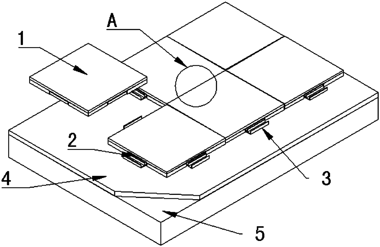
[0024] figure 1 A schematic structural view of a ground laying system according to an embodiment of the present invention is shown, as figure 1 As shown, the ground laying system of the embodiment of the present invention includes: a leveling layer 4 , fasteners 3 , clips 2 and a floor 1 , and the leveling layer 4 is set on the original ground 5 . The fastener 3 is fixedly connected with the leveling layer 4, the fastener 2 is installed on the floor 1, and the fastener 2 is engaged with the fastener 3 to fix the floor on the ground. The fixed connection means that there will be no relative movement between the fastener 3 and the leveling layer 4 .
[0025] The floor in the embodiment of the present invention can be a common standard board, such as a 300mm*300mm solid composite board, a 300mm*600mm solid composite board, a 600mm*600mm solid composite board, etc.; it can also be a parquet standard board, such as a solid waveguide board (its width*length=150*600mm), solid trian...
Embodiment 2
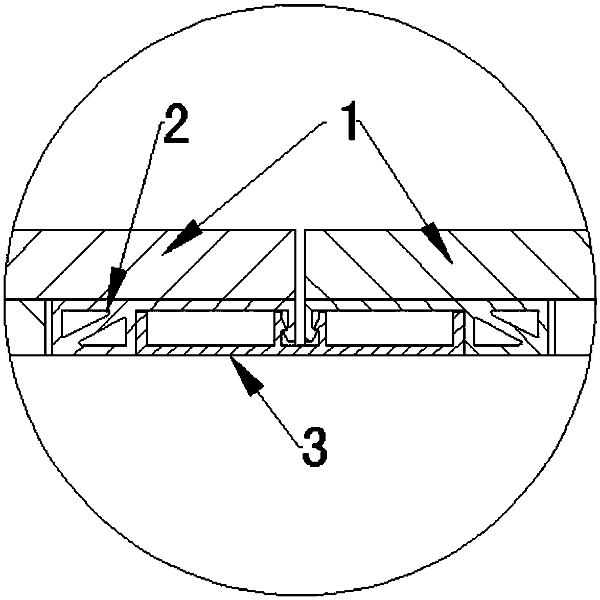
[0032] On the basis of the first embodiment above, optionally, as image 3 and Figure 4 As shown, the fastener 3 includes a fastener body, and the fastener body has a slot 31 , and the opening of the slot 31 faces away from the ground. The two inner groove walls of the slot 31 are provided with first protrusions 32, and the clip 2 is inserted into the slot 31, and is clamped between the two first protrusions 32, so that the clip 2 is better connected with the buckle. Part 2 is clipped to ensure that the floor 1 is firmly installed on the ground. The first protrusion 32 can also prevent the second protrusion 23 of the clip 2 from contacting the inner groove wall of the fastener 2 during the sliding down process, so as to avoid unnecessary wear of the second protrusion 23 .
[0033] In a preferred embodiment of the present invention, as image 3 and Figure 5 As shown, the clip 2 includes a clip body 21 and a hook, and the clip body 21 is connected to the bottom of the floo...
Embodiment 3
[0050] Based on the ground laying system of Embodiment 1 or Embodiment 2 above, the embodiment of the present invention also provides a ground laying method, such as Figure 7 shown, which includes:
[0051] S110, leveling the original ground to form a leveling layer;
[0052] After the foundation is cleaned on the leveling layer, the wires shall be sprung according to the requirements of the pavement design drawings. Use a ruler to check the accuracy of the leveling layer within 2㎡. If the drop of the leveling layer is obviously greater than or equal to 2mm / 2㎡, it needs to be marked at this position. When the floor is paved to this position, fill it with fine-tuning leveling glue , to level the screed.
[0053] S120, installing fasteners on the leveling layer;
[0054] Fasteners can be installed on screeds using stress nails.
[0055] S130, installing the clip on the floor;
[0056] S140, snapping the fastening piece and the fastening piece together, and fixing the floor...
PUM
 Abstract
Description
Claims
Application Information