intake valve of internal combustion engine
An internal combustion engine and intake valve technology, applied in mechanical equipment, engine components, machines/engines, etc., can solve the problems of intake valve accumulation, small self-cleaning function, and limited deposit reduction effect.
- Summary
- Abstract
- Description
- Claims
- Application Information
AI Technical Summary
Problems solved by technology
Method used
Image
Examples
no. 1 approach
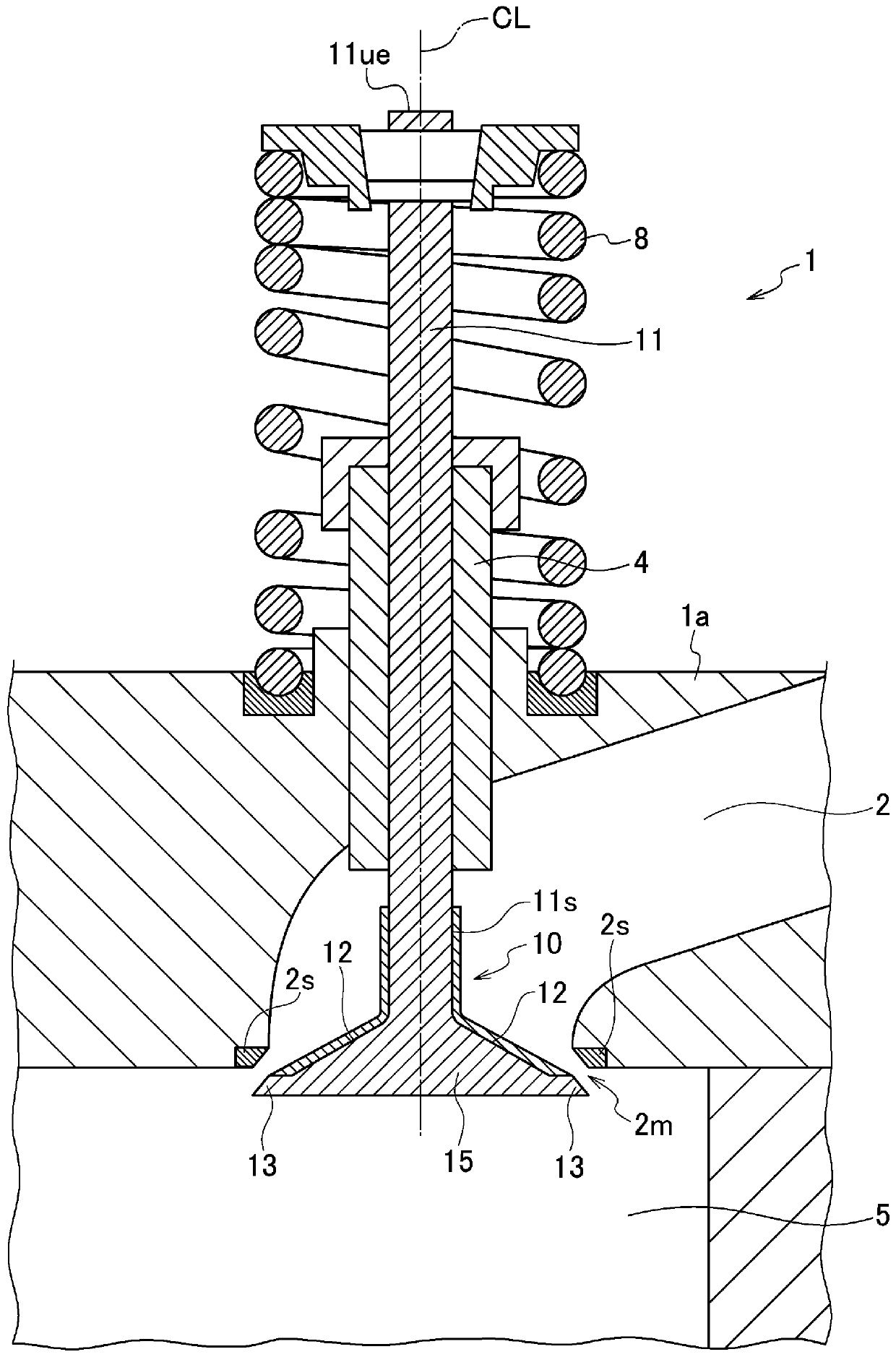
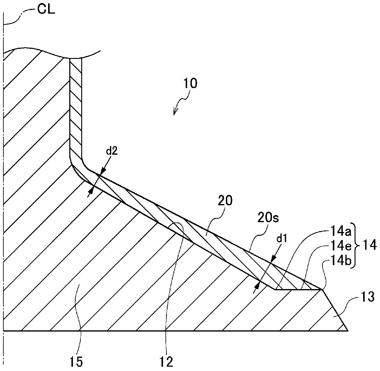
[0059] refer to figure 1 and figure 2 , the intake valve of the internal combustion engine according to the first embodiment of the present invention will be described. figure 1 It is a sectional view of the intake valve of the internal combustion engine of the first embodiment. figure 2 It is an enlarged sectional view of main parts of the intake valve of the first embodiment.
[0060] Such as figure 1As shown, the intake valve 10 of the internal combustion engine 1 is provided to open and close the intake port 2m of the intake port 2 of the cylinder head 1a. The intake valve 10 has a valve head 15 and a valve shaft portion 11, the valve head 15 corresponds to the intake port 2m, the intake port 2m communicates with the combustion chamber 5 of the internal combustion engine 1, and the valve shaft portion 11 is arranged to cross the intake port 2 And protrude outward from the cylinder head 1a. The valve shaft portion 11 is supported by the shaft guide 4 so as to recipro...
no. 2 approach
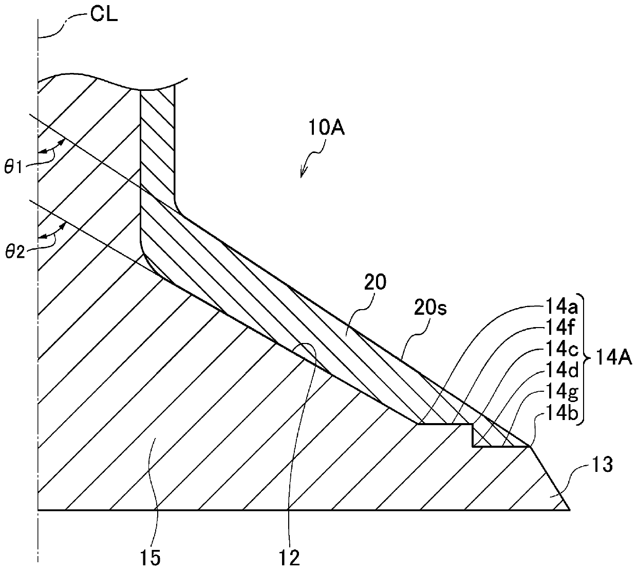
[0071] image 3 It is an enlarged cross-sectional view of main parts of the intake valve of the second embodiment. The intake valve 10A of the second embodiment differs from the intake valve 10 of the first embodiment in the structure of the stepped portion 14A and the coating 20A. Except for this point, similar to the first embodiment, in image 3 in, right with figure 1 or figure 2 The same reference signs are assigned to common components.
[0072] Such as image 3 As shown, the step portion 14A of the present embodiment is formed in a two-stage step shape, and has a first boundary portion 14a, a second boundary portion 14b, a third boundary portion 14c, and a fourth boundary portion 14d. On the step portion 14A, between the first boundary portion 14a and the third boundary portion 14c, an inclined flat surface 14f having an inclination angle smaller than that of the umbrella-shaped inclined portion 12 is formed, and between the fourth boundary portion 14d and the sec...
no. 3 approach
[0077] Figure 4 It is an enlarged cross-sectional view of main parts of an intake valve according to a third embodiment. The intake valve 10B of the third embodiment differs from the intake valve 10 of the first embodiment in the structure of the umbrella-shaped inclined portion 12B and the coating 20B. Except for this point, similar to the first embodiment, in Figure 4 in, right with figure 1 or figure 2 The same reference signs are assigned to common components.
[0078] Such as Figure 4 As shown, the entire surface of the umbrella-shaped inclined portion 12B in this embodiment other than the stepped portion 14 is formed as a curved surface that is concave toward the front end surface side of the valve head 15 . In this embodiment, as in the first embodiment, an oil-repellent coating is formed on the umbrella-shaped inclined portion 12B including the stepped portion 14 and a part of the surface of the valve shaft portion 11 connected to the umbrella-shaped inclined ...
PUM
 Abstract
Description
Claims
Application Information
 - R&D
- Intellectual Property
- Life Sciences
- Materials
- Tech Scout
- Unparalleled Data Quality
- Higher Quality Content
- 60% Fewer Hallucinations
Browse by: Latest US Patents, China's latest patents, Technical Efficacy Thesaurus, Application Domain, Technology Topic, Popular Technical Reports.
© 2025 PatSnap. All rights reserved.Legal|Privacy policy|Modern Slavery Act Transparency Statement|Sitemap|About US| Contact US: help@patsnap.com


