Ceiling light special for D type ceiling and mounting process of ceiling light

A technology for ceiling and ceiling lamps, which is applied in the field of ship electrical and outfitting, can solve the problems of inconvenient installation and waste of ceiling materials, and achieve the effects of stable structure, high adaptability and beautiful appearance.

Pending Publication Date: 2018-07-10
福建省福船海洋工程技术研究院有限公司
View PDF0 Cites 0 Cited by
  • Summary
  • Abstract
  • Description
  • Claims
  • Application Information

AI Technical Summary

Problems solved by technology

[0002] The D-shaped ceiling includes a tank body and more than two cover plates. The cover plates are embedded in the notch of the tank body and the two adjacent cover plates are separated from each other to form an installation opening. Due to its thin and long characteristics, it is used as One of the important raw materials for ship outfitting is very popular. However, the arrangement of dome lights on D-shap

Method used


Image

  • Ceiling light special for D type ceiling and mounting process of ceiling light
  • Ceiling light special for D type ceiling and mounting process of ceiling light

Examples


Embodiment 1

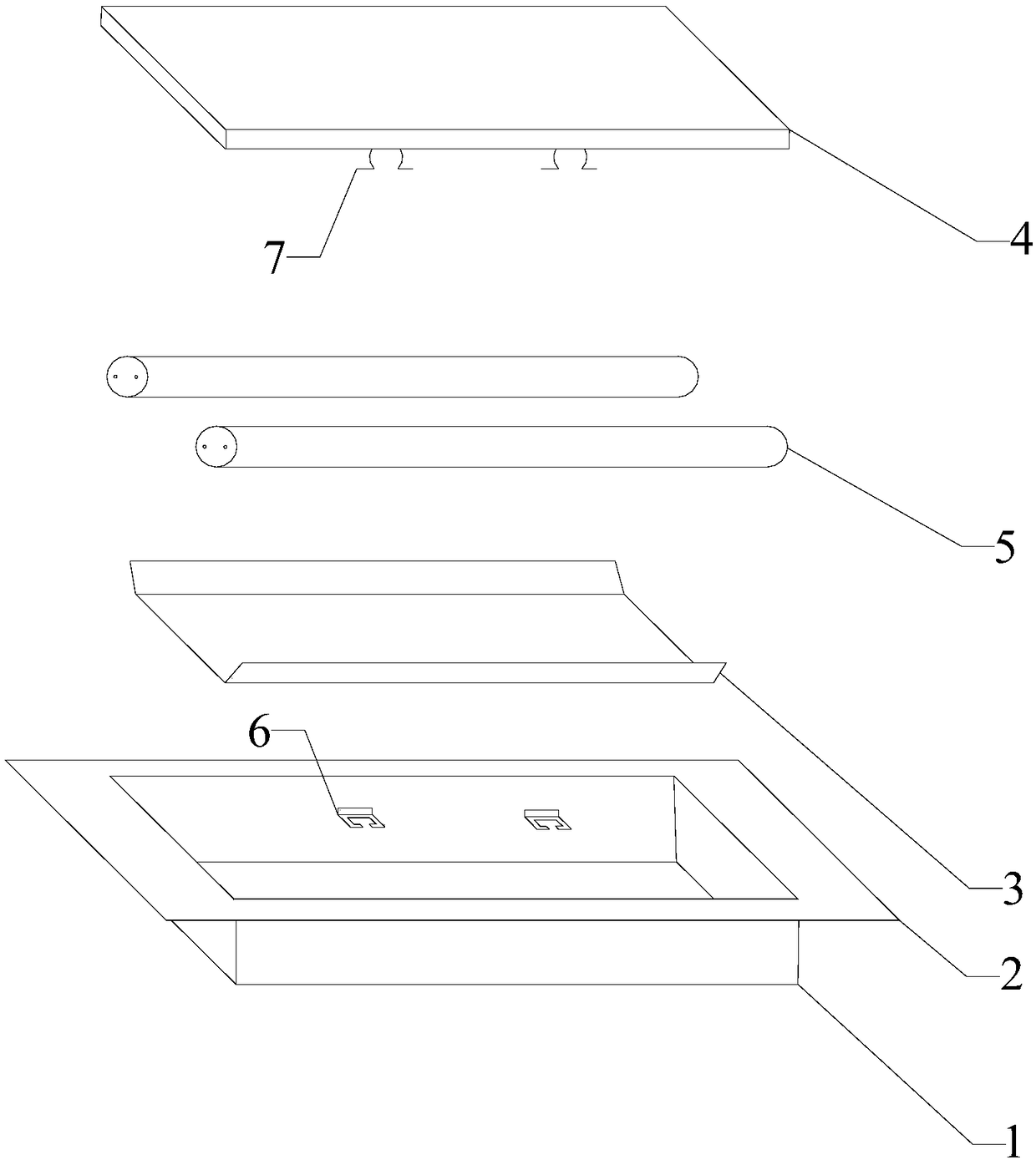
[0043] Please refer to figure 1 and figure 2 Shown, embodiment one of the present invention is:

[0044]A dome lamp dedicated to a D-shaped ceiling, comprising a housing 1, a frame 2, a reflector 3, a lamp panel 4 and a lamp tube 5. The outline of the housing 1 is a cuboid and one end of the housing 1 has an opening. The housing 1 The outer diameter of the body 1 is adapted to the inner diameter of the installation opening of the D-shaped ceiling. The frame 2 is sleeved on the opening end of the housing 1 and fixed with the housing 1. The inner side of the bottom plate of the housing 1 is connected with the shell The inner studs of the bottom plate of the body 1 are perpendicular to each other, the reflector 3 is connected with the inner side of the bottom plate of the housing 1 through the inner studs, and the two ends of the reflector 3 and the two short sides of the housing 1 are respectively A lamp holder and a starter are provided, and the lamp holder and the starter a...

Embodiment 2

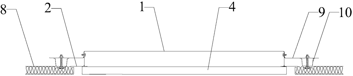
[0047] A dome lamp dedicated to a D-shaped ceiling, which has the following features on the basis of Embodiment 1: It also includes an L-shaped angle steel 9, the number of which is two, and the two angle steels 9 are respectively symmetrically arranged on the housing 1, the angle steel 9 is composed of a first steel plate and a second steel plate perpendicular to each other, the first steel plate and the second steel plate are rectangular and the long side end of the first steel plate is connected to the long side end of the second steel plate connected, the first steel plate is connected to the outside of the side wall of the housing 1, a hanging beam 10 is provided between the second steel plate and the cover plate 8, and the second steel plate passes through the connection between the hanging beam 10 and the cover plate 8 Inner surface connection.

[0048] During installation, the frame 2 is fixed on the upper surfaces of two adjacent cover plates 8, the second steel plate...


PUM


Abstract

The invention relates to a ceiling light special for a D type ceiling and a mounting process of the ceiling light. The ceiling light comprises a shell, a frame, a reflecting plate, a light panel and alight tube. An opening is formed in one end of the shell, the open end of the shell is sleeved with the frame, and the frame is fixed to the shell. The reflecting plate is connected with the inner side of a bottom plate of the shell, and the inner sides of side plates of the shell are perpendicularly connected with clamping plates. Buckles matched with the clamping plates are arranged on the panel face of the light panel, and the light panel is fixed to the open end of the shell through the buckles and the clamping plates. The light tube is arranged between the reflecting plate and the lightpanel, and the two ends of the light tube are fixed to the inner side of the bottom plate of the shell. The reflecting plate and the light tube are mounted in the shell of the ceiling light, meanwhile, the shell is embedded into a mounting opening between two adjacent cover plates, and the shell is fixed to the two adjacent cover plates through the frame.

Description

technical field [0001] The invention relates to the field of ship electrical and outfitting, in particular to a special dome light for a D-shaped ceiling and an installation process thereof. Background technique [0002] The D-shaped ceiling includes a tank body and more than two cover plates. The cover plates are embedded in the notch of the tank body and the two adjacent cover plates are separated from each other to form an installation opening. Due to its thin and long characteristics, it is used as One of the important raw materials for ship outfitting is very popular. However, the arrangement of dome lights on D-shaped ceilings is no different from that on other types of ceilings. It is necessary to precisely dig a hole in the middle of the ceiling. The size of the hole needs to be consistent with the The size of the lamps embedded in the ceiling is the same. Due to the construction environment and space on the ship, the installation is very inconvenient, and at the sam...

Claims


Application Information

Patent Timeline
IPC IPC(8): F21S9/02F21V17/12F21V17/16F21V21/04F21V23/02
CPCF21S9/02F21V17/12F21V17/164F21V21/041F21V23/026
Inventor 殷文林
Owner 福建省福船海洋工程技术研究院有限公司
Why Eureka
Try Eureka