
Self-cleaning router with storable antenna

A router and antenna technology, applied in the information field, can solve the problems of easy generation of dust and manual cleaning, and achieve the effect of facilitating storage and transportation

Inactive Publication Date: 2018-07-10
河南趣读信息科技有限公司
View PDF1 Cites 0 Cited by
  • Summary
  • Abstract
  • Description
  • Claims
  • Application Information

AI Technical Summary

Problems solved by technology

[0004] The purpose of the present invention is to provide a router with self-cleaning function in order to solve the problem in the prior art that the router is prone to dust and needs manual cleaning during long-term use. Self-cleaning, has a good cleaning effect and reduces manual waste, and has a retractable antenna, which is convenient for the storage and transportation of the router

Method used


Image

  • Self-cleaning router with storable antenna
  • Self-cleaning router with storable antenna
  • Self-cleaning router with storable antenna

Examples


Embodiment 1

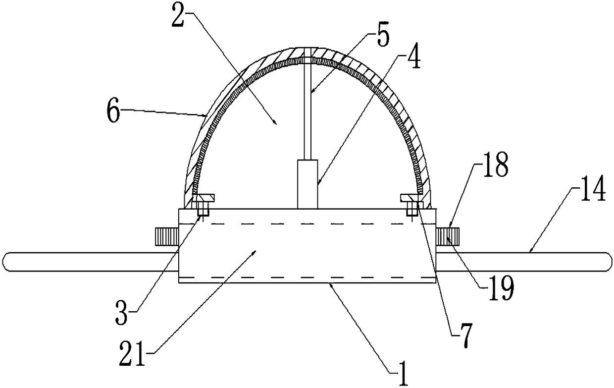
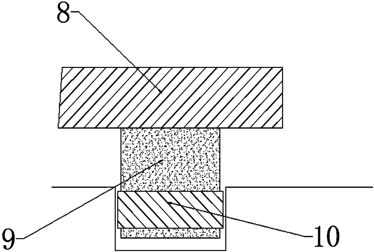
[0031] A router with self-cleaning function includes a base 1, a hemispherical casing 2 arranged on the base 1, a circular groove 3 is arranged on the base 1, a motor 4 is arranged in the middle of the base 1, Described motor 4 comprises motor main shaft 5, and described motor main shaft 5 passes through described hemispherical casing 2, and the surface of described hemispherical casing 2 is provided with brush bar 6, and described brush bar 6 is hemispherical, and described The middle part of the brush bar 6 is connected with the other end of the motor main shaft 5, the brush bar 6 is close to the hemispherical casing 2, and both ends of the brush bar 6 are provided with a sliding mechanism 7, and the sliding ends of the sliding mechanism 7 Placed in the circular groove 3, the motor 4 can provide rotational power inside the hemispherical casing 2, the motor spindle 5 passes through the hemispherical casing 2, and the other end of the motor spindle 5 is connected with Brush ba...

Embodiment 2

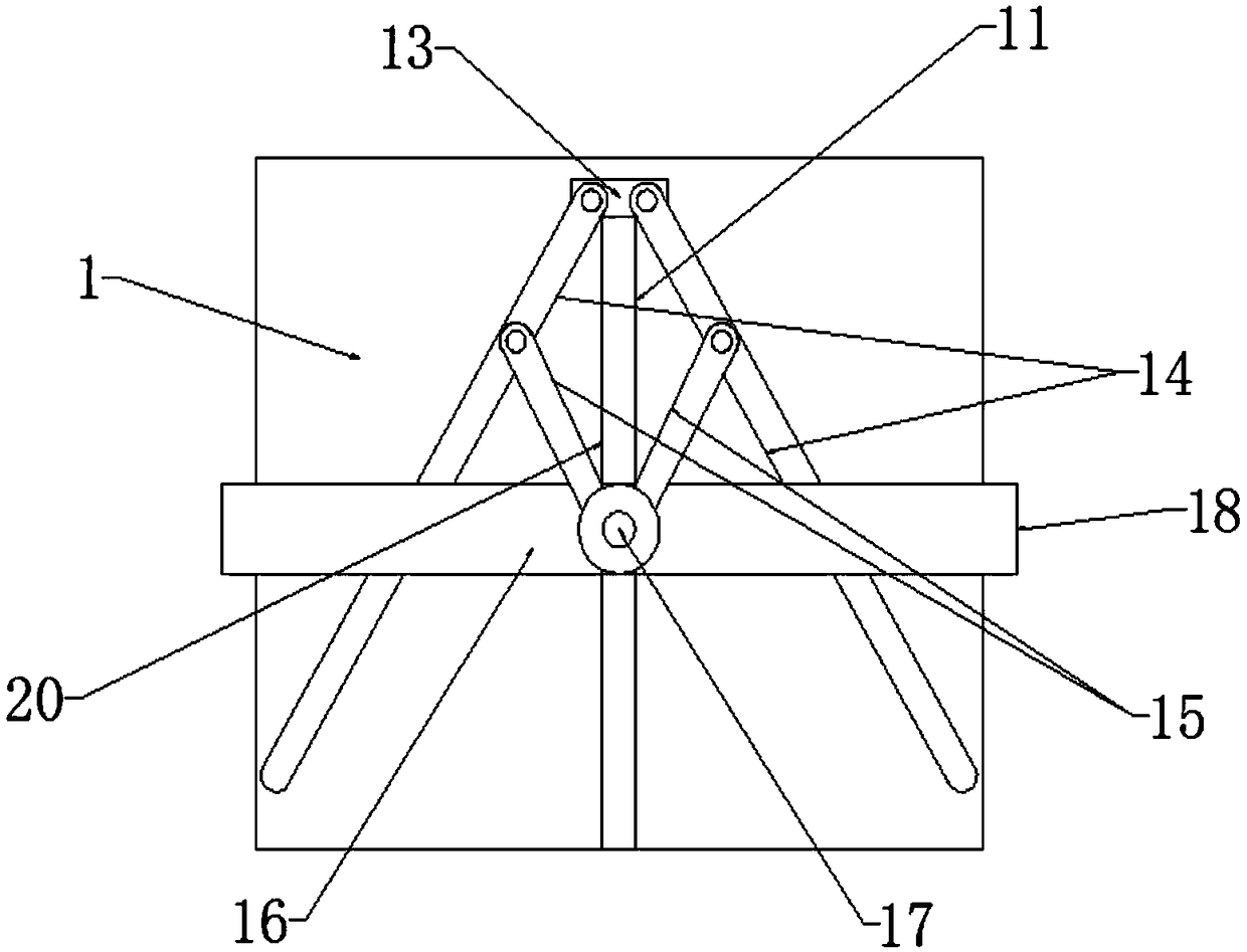
[0033] On the basis of Embodiment 1, the antenna storage mechanism includes a chute 11 placed on the base 1, one end of the chute 11 is fixed with a hinged seat 13, and the two ends of the hinged seat 13 are hinged with an antenna 14 One end of the antenna 14 near the hinge seat 13 is also hinged with a slide bar 15, the other end of the slide bar 15 is hinged with a slide plate 16, the other end of the slide bar 15 is hinged at the middle part of the slide plate 16, and the slide plate 16 The middle part is provided with a slide block 17, and the slide block 17 is placed in the chute 11, and the slide plate 16 slides on the path of the chute 11, so that the antenna 14 can be rotated and contracted, so that the antenna 14 can pass through the antenna slot 21 is accommodated in the base 1.

Embodiment 3

[0035] On the basis of Embodiment 2, both ends of the slide plate 16 are toggle ends 18, and the toggle ends 18 are provided with a friction surface 19, and the toggle end 18 is toggled by hand, so that the slide plate 16 can drive The antenna 14 rotates.


PUM


Abstract

The invention discloses a self-cleaning router with a storable antenna, belonging to a router in the field of information technology, and aiming to provide the self-cleaning router with the storable antenna. The technical scheme of the invention is that: the self-cleaning router comprises a base and a hemispherical casing arranged on the base, wherein the base is provided with a circular groove, amotor is arranged at the middle position of the base, the motor comprises a motor spindle, and the motor spindle penetrates through the hemispherical casing, a brush rod is arranged on the surface ofthe hemispherical casing, both ends of the brush rod are provided with a sliding mechanism, a sliding end of the sliding mechanism is arranged in the circular groove, the base comprises a built-in antenna storage mechanism, antenna slots are opened on both sides of the base, and the antenna storage mechanism comprises an antenna. The self-cleaning router disclosed by the invention has a good cleaning effect, can reduce the waste of labor, also has the storable antenna, and can facilitate the storage and transportation of the router.

Description

technical field [0001] The invention belongs to the field of information technology, and in particular relates to a router with a self-cleaning function. Background technique [0002] A router is a network device used to forward electrical signals. It can provide an exclusive electrical signal path for any two network nodes connected to the router. The most common routers are Ethernet routers. Other common ones are telephone voice routers, fiber optic routers, etc. The main functions of routers include physical addressing, network topology, error checking, frame sequence, and flow control. At present, routers also have some new functions, such as support for VLAN (virtual local area network), support for link aggregation, and some even have the function of firewall. Generally speaking, each port of a router is used to connect an independent network segment, but sometimes in order to provide faster access speed, we can directly connect some important network computers to ...

Claims


Application Information

Patent Timeline
IPC IPC(8): H04L12/771B08B1/04H04L45/60
CPCH04L45/60B08B1/12B08B1/32
Inventor 刘鹏亚
Owner 河南趣读信息科技有限公司
Learn More