
Deep cavity injection mold achieving easy demolding

An injection mold and deep cavity technology, applied in the field of deep cavity injection molds, can solve the problems of high work intensity, damage to molds and operators, difficult air pins, etc., and achieve the effect of easy opening

Inactive Publication Date: 2018-07-13
漳州市龙文区仁信工业设计有限公司
View PDF0 Cites 16 Cited by
  • Summary
  • Abstract
  • Description
  • Claims
  • Application Information

AI Technical Summary

Problems solved by technology

[0003] In practical application, when the existing air pins are used for demoulding of deep-cavity products, because the product is close to the upper surface of the air pins and resists the air pins, it is difficult to open the air pins outward, and it is very easy to increase the air pressure to make the air pins If the core is punched out, the product will be damaged and even the mold and the operator will be injured. It is also easy to whiten, break or deform the product. It is necessary to increase the amount of release agent sprayed on the mold cavity, or use a hot air blower to blow the product Elimination of hot air at the top white spot, resulting in high work intensity, low efficiency, high rate of defective products, and high overall cost

Method used


Image

  • Deep cavity injection mold achieving easy demolding
  • Deep cavity injection mold achieving easy demolding
  • Deep cavity injection mold achieving easy demolding

Examples


Embodiment Construction

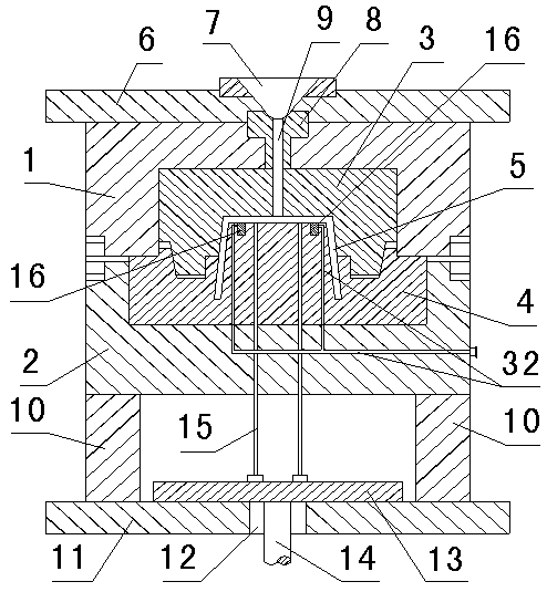
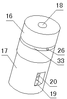
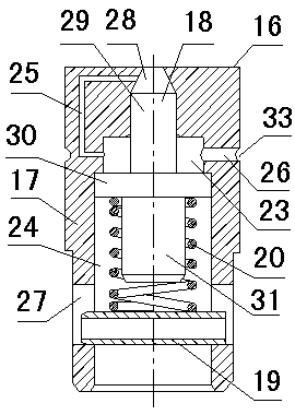
[0023] Such as Figure 1~5 As shown, an embodiment of the present invention, a deep cavity injection mold that is easy to demould, comprises adjacent fixed mold 1 and movable mold 2; The cavity surrounded by the lower mold core 4, the upper mold core 3 and the lower mold core 4 is a mold cavity 5 for injection molding; the fixed mold 1 is provided with a fixed mold seat plate 6, and a fixed mold seat plate 6 A gate 7 is arranged in the middle, and a sprue sleeve 8 is provided under the gate 7, and an injection runner 9 connecting the gate 7 and the mold cavity 5 is provided in the middle of the sprue sleeve 8 and the upper mold core 3; Die feet 10 are arranged on both sides below the mold 2, and a movable mold seat plate 11 is arranged under the mold foot 10. A perforation 12 is provided in the middle of the movable mold seat plate 11. A top plate 13 is arranged in the middle of the mold feet 10 on both sides. The main top of the injection molding machine The rod 14 passes th...


PUM


Abstract

The invention relates to a deep cavity injection mold achieving easy demolding. The deep cavity injection mold comprises a fixed mold, a moving mold, an upper mold core, a lower mold core, a mold cavity, a fixed mold seat plate, a sprue, a sprue sleeve, a glue injection runner, mold feet, a moving mold seat plate, an ejector plate and ejector rods. Air pins are arranged in the lower mold core, andeach air pin comprises a body with a through hole formed in the center, an ejector pin, a thrust pin and a spring. Each through hole is composed of a trapezoidal hole, a second hole, a third hole anda lower hole. An air guide hole communicating with the corresponding trapezoidal hole and third hole is formed in each body. An air inlet hole is formed in the inner wall of each third hole. A thrustpin hole is formed in the lower portion of each lower hole, and each thrust pin is inserted in the corresponding thrust pin hole. Each ejector pin is composed of an airtight segment, a guide segment,a protruding shoulder and a spring guide rod. Each spring is arranged on the outer portion of the corresponding spring guide rod in a sleeving manner, and the protruding shoulders are pushed towardsthe third holes so as to abut against the lower edges of the third holes. When the air pins of the deep cavity injection mold work, the ejector pins are opened inwards, opening is easy, an injection molded product and the mold are separated completely by compressed air, and the situation that the injection molded product is ejected to be white or be broken or deform cannot happen.

Description

technical field [0001] The invention relates to the technical field of injection molds, in particular to a deep-cavity injection mold that is easy to demould. Background technique [0002] Injection molding is a common method for producing injection molded products. Specifically, it refers to injecting heated and melted materials into the mold cavity under high pressure, and after cooling and solidifying, molded products are obtained. In the process of injection molding, in order to make the product fall out of the mold cavity smoothly after molding, an ejector mechanism is usually used to push the product out. In injection molding products, container products such as barrels, boxes, and boxes with closed walls, bottoms, and cavity depths greater than five times the wall thickness are called deep cavity products. Due to the coating between the deep cavity product and the mold core The large force, combined with the effect of stickiness and negative pressure, makes it diffic...

Claims


Application Information

Patent Timeline
IPC IPC(8): B29C45/26B29C45/40B29C45/43
CPCB29C45/2602B29C45/4005B29C45/43
Inventor 黄志远
Owner 漳州市龙文区仁信工业设计有限公司
Learn More