Supercharge Your Innovation With Domain-Expert AI Agents!

Feed mechanism assembled by fitting optical adhesive on polaroid

A technology of optical glue and polarizer, applied in the direction of conveyor objects, transportation and packaging, chemical instruments and methods, etc., can solve the problems of sheet material retention, poor versatility, and suction nozzle components can not normally absorb the sheet material, etc., to achieve improved success High efficiency and good versatility

Inactive Publication Date: 2018-07-13
荣旗工业科技(苏州)股份有限公司
View PDF6 Cites 5 Cited by
  • Summary
  • Abstract
  • Description
  • Claims
  • Application Information

AI Technical Summary

Problems solved by technology

[0002] Polarizer bonding optical glue assembly equipment is the equipment that attaches the sheet material to the base film according to the specified position. Before lamination, a feeding mechanism is required to peel off the protective film from the sheet material and supply the sheet material to the designated position, waiting for suction. The nozzle mechanism absorbs the sheet material; the existing feeding mechanism can only be applied to a single-size material roll, which has poor versatility; it is difficult to maintain the flatness of the material belt when the suction nozzle mechanism absorbs the sheet material, resulting in the suction nozzle assembly not being able to normally absorb the sheet material , the sheet material tends to stay on the material belt, causing the equipment to fail to complete the bonding process normally

Method used


Image

  • Feed mechanism assembled by fitting optical adhesive on polaroid
  • Feed mechanism assembled by fitting optical adhesive on polaroid

Examples


Embodiment Construction

[0012] The preferred embodiments of the present invention will be described in detail below in conjunction with the accompanying drawings, so that the advantages and features of the present invention can be more easily understood by those skilled in the art, so as to define the protection scope of the present invention more clearly.

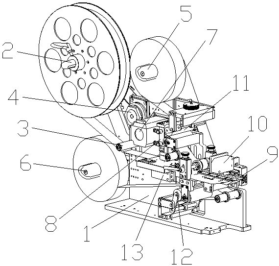
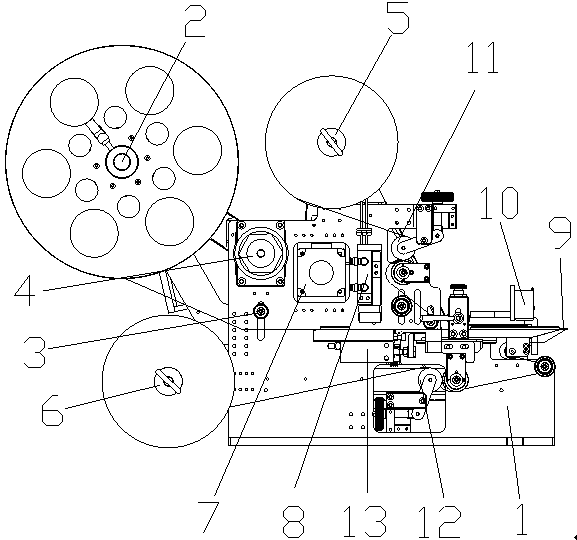
[0013] see figure 1 and figure 2 , the embodiment of the present invention includes:

[0014] A feeding mechanism assembled with a polarizer laminated with optical glue, comprising: a support plate 1, a feeding shaft 2, a feeding guide shaft 3, a torque limiter 4, an upper layer receiving shaft 5, a lower layer receiving shaft 6, a stepping Motor 7, upper layer pulling mechanism, lower layer pulling mechanism, pressing cylinder 8, stripping knife 9, stripping knife cylinder 13, sensor 10 and sensor cylinder; described discharging shaft 2 is arranged on support plate 1 one end, and described upper layer receives The material shaft 5 is located ...


PUM


Abstract

The invention discloses a feed mechanism assembled by fitting an optical adhesive on a polaroid. The feed mechanism comprises a support plate, an emptying shaft, an emptying guide shaft, a torque limiter, an upper layer material receiving shaft, a lower layer material receiving shaft, a stepping motor, an upper layer material pulling mechanism, a lower layer material pulling mechanism, a peeling knife, and a peeling knife cylinder; the emptying shaft, the upper layer material receiving shaft, the lower layer material receiving shaft and the emptying guide shaft are arranged on the support plate, the torque limiter is linked with the emptying shaft; the stepping motor is respectively in drive joint with the upper layer material receiving shaft and the lower layer material receiving shaft; the support plate is provided with a peeling knife slide groove, the peeling knife is arranged on the peeling knife slide groove; a piston rod of the peeling knife cylinder is connected and fixed withthe tail end of the peeling knife; the upper layer material pulling mechanism and the upper layer material receiving shaft are arranged correspondingly, and the lower layer material pulling mechanismand the lower layer material receiving shaft are arranged correspondingly. Through the above mode, a sheet stock is stably and efficiently provided, the smoothness of a material belt is guaranteed, the success rate of a suction nozzle sucking up the sheet stock is increased; the width of a mechanism locating the material belt is adjustable, so that the feed mechanism is suitable for the material belts of different widths and is good in universality.

Description

technical field [0001] The invention relates to the field of feeding mechanisms for chip mounters, in particular to a feeding mechanism for assembling polarizers with optical glue. Background technique [0002] Polarizer bonding optical adhesive assembly equipment is the equipment that attaches the sheet material to the base film according to the specified position. Before lamination, a feeding mechanism is required to peel off the protective film from the sheet material and supply the sheet material to the designated position, waiting for suction. The nozzle mechanism absorbs the sheet material; the existing feeding mechanism can only be applied to a single-size material roll, which has poor versatility; it is difficult to maintain the flatness of the material belt when the suction nozzle mechanism absorbs the sheet material, resulting in the suction nozzle assembly not being able to normally absorb the sheet material , the sheet material tends to stay on the material belt,...

Claims


Application Information

Patent Timeline
IPC IPC(8): B32B38/10B65G47/91
CPCB32B38/10B65G47/91
Inventor 汪炉生钱曙光柳洪哲柳云鸿罗时帅
Owner 荣旗工业科技(苏州)股份有限公司
Features
  • R&D
  • Intellectual Property
  • Life Sciences
  • Materials
  • Tech Scout
  • Unparalleled Data Quality
  • Higher Quality Content
  • 60% Fewer Hallucinations
Learn More