Box structure based on riveting

A box structure and riveting technology, which is applied in the field of rail vehicles, can solve problems such as difficulty in guaranteeing dimensional accuracy, few procurement channels, and heavy workload, and achieve the effects of guaranteed sealing level, high dimensional accuracy, and short production hours

Active Publication Date: 2019-08-27
CRRC QINGDAO SIFANG ROLLING STOCK RES INST
View PDF7 Cites 0 Cited by
  • Summary
  • Abstract
  • Description
  • Claims
  • Application Information

AI Technical Summary

Problems solved by technology

However, the welding of the frame 202 has the following disadvantages: the dimensional tolerance and shape tolerance of the product are difficult to guarantee, and it takes a lot of man-hours to reshape, especially for stainless steel welded structures and aluminum alloy welded structures, the man-hours of reshaping even exceed the welding man-hours; Compared with the base metal, the fatigue strength of the area is greatly reduced. In order to ensure the strength of the product, the weight of the product usually increases; moreover, there is a problem that different metals cannot be welded, and some strength requirements for steel boxes are not sufficient. The high position cannot be replaced by light materials such as aluminum alloy to reduce the overall weight of the box; moreover, in order to reduce the amount of welding, the "welded frame + skin riveting" process is adopted, because the dimensional accuracy of the frame 201 is difficult to guarantee, The rivet holes on the frame 201 need to be drilled, and the workload is relatively large; finally, the frame 201 is generally welded by profiles, and the large purchase quantities of profiles, long delivery period and few procurement channels are very unfavorable to the organization of production

Method used


Image

  • Box structure based on riveting
  • Box structure based on riveting
  • Box structure based on riveting

Examples


Embodiment Construction

[0022] In order to make the purpose, technical solution and advantages of the present invention clearer, the embodiments of the present invention will be further described in detail below in conjunction with the accompanying drawings.

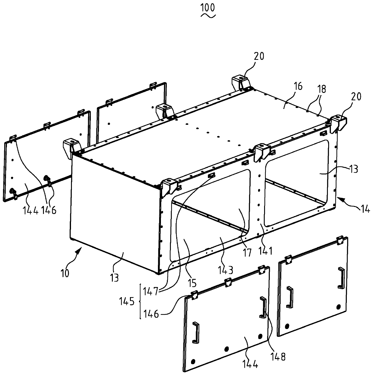
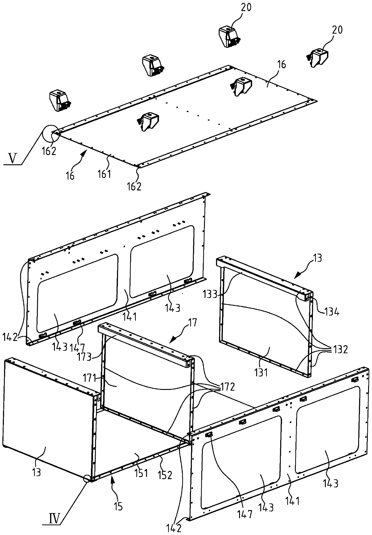
[0023] figure 2 It is a structural schematic diagram of the box structure based on riveting of the present invention, image 3 is a disassembled view of a riveted-based box structure without a door panel. Specifically, see Figure 2 to Figure 3 , the box structure 100 based on riveting of the present invention includes a box body 10 and lifting lugs 20 .

[0024] The box body 10 includes a first vertical board 13 , a second vertical board 14 , a bottom board 15 , a top board 16 , a middle partition board 17 , and rivets 18 .

[0025] There are two first vertical plates 13 arranged vertically and parallel to each other at intervals. The first vertical plate 13 includes a first vertical plate body 131 , a first bending portion 132 , and a rei...


PUM


Abstract

The invention discloses a riveting-based tank body structure which comprises a tank body and lifting lugs; the tank body comprises first vertical plates, second vertical plates, a bottom plate and a top plate; each first vertical plate comprises a first vertical plate body and first bent parts; the first bent parts perpendicular to each first vertical plate body are arranged on the same side of the four edges of each first vertical plate body; each second vertical plate comprises a second vertical plate body and second bent parts; the second bent parts perpendicular to each second vertical plate body are arranged on the same side of the upper end and the lower end of each second vertical plate body respectively; the bottom plate and the top plate are horizontally arranged in parallel; thefirst vertical plates and the second vertical plates are vertically arranged, are mutually perpendicular and all perpendicular to the bottom plate and the top plate; the first bent parts are abutted to the second vertical plate bodies, the second bent parts, the bottom plate and the top plate respectively and are in riveting connection with the second vertical plate bodies, the second bent parts,the bottom plate and the top plate to form the tank body; and the lifting lugs are arranged on the upper side of the front side or the back side of the tank body and are detachably and fixedly connected with the tank body. The tank body structure is formed by riveting the plates and ensures the sealing grade of the tank body while considering the strength.

Description

technical field [0001] The invention relates to the technical field of rail vehicles, in particular to a box structure based on riveting. Background technique [0002] At present, the undercarriage suspension equipment of rail vehicles, such as traction and other electrical system components, are usually installed through a box body, and the box body is usually processed by welding, riveting or a combination of the two. [0003] see figure 1 As shown, the box body 200 includes a frame 201 and a skin 202 , the frame 201 is welded, and the skin 202 is riveted to the frame 201 by rivets 203 . However, the welding of the frame 202 has the following disadvantages: the dimensional tolerance and shape tolerance of the product are difficult to guarantee, and it takes a lot of man-hours to reshape, especially for stainless steel welded structures and aluminum alloy welded structures, the man-hours of reshaping even exceed the welding man-hours; Compared with the base metal, the fat...

Claims


Application Information

Patent Timeline
Patent Type & Authority Patents(China)
IPC IPC(8): B61C17/00H05K5/00
Inventor 王长昌薛浩飞徐先伟
Owner CRRC QINGDAO SIFANG ROLLING STOCK RES INST
Why Eureka
Try Eureka