
Adjustable jet pump

A jet pump, adjustable technology, used in jet pumps, non-displacement pumps, pumps, etc., can solve problems such as time-consuming

Active Publication Date: 2022-04-29
CHENGDU TUERSI TECH
View PDF13 Cites 0 Cited by
  • Summary
  • Abstract
  • Description
  • Claims
  • Application Information

AI Technical Summary

Problems solved by technology

Since the jet pump has a variety of nozzles and throat sizes, in actual use, under different working conditions, it is necessary to replace the combination of nozzles and throats of different sizes to match the working conditions, while conventional jet pumps can only be disassembled several times. to replace jet pump nozzles, time consuming

Method used


Image

  • Adjustable jet pump
  • Adjustable jet pump
  • Adjustable jet pump

Examples


Embodiment 1

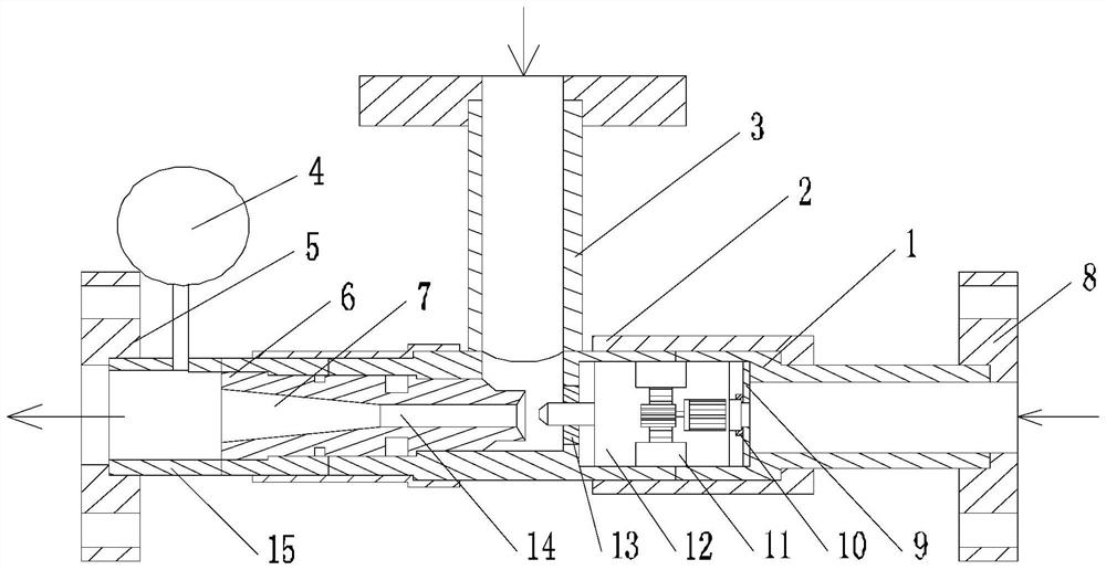
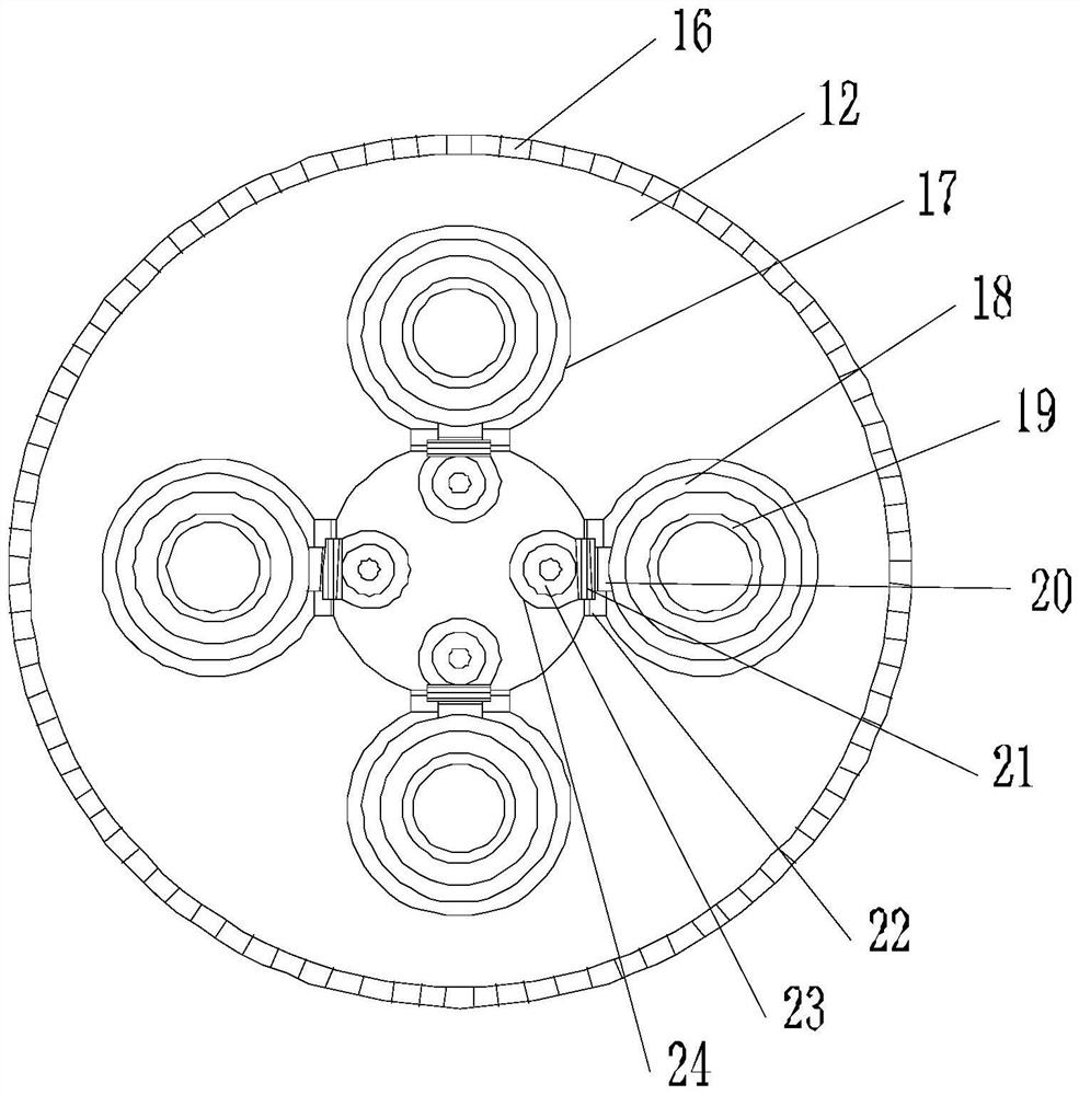
[0034] Such as Figures 1 to 8 As shown, this embodiment includes a pump body 1, the two ends of the pump body 1 are respectively connected with a first flange 5 and a second flange 8, and a connecting pipe 3 is provided in the middle of the pump body 1, and the pump body 1 On the inner wall at one end close to the first flange 5, there are intercommunicating diffusion channels 7 and throats 14, and on the inner wall at one end close to the second flange 8 of the pump body 1, two baffles 9 are arranged. , two baffles 9 form a conversion chamber in the pump body 1, and an arc-shaped base is provided on the inner wall of the bottom of the conversion chamber. An annular toothed belt 16 is arranged on the circumferential wall, and two driving motors are arranged on the side wall of the conversion chamber. The output end of the driving motor is provided with a driving gear meshed with the annular toothed belt 16, and along the axial direction of the runner 12 There are a plurality...

Embodiment 2

[0041] Such as Figures 1 to 8As shown, on the basis of Embodiment 1, this embodiment also includes a locking assembly. The locking assembly includes a planet carrier 44, a main gear 52, a fixed ring 50, a rotating rod 49 and a connecting rod 30. The main gear 52 is fixed on the bidirectional motor On one output end of 24, the main gear 52 is connected with the connecting rod 30 through the rotating rod 49, and the connecting rod 30 is connected with the worm wheel 21. The outer diameter of the rotating rod is larger than the diameter of the connecting rod 30, and a plurality of planetary gears 43 are distributed symmetrically in rotation. On the planet carrier 44, and a plurality of planetary gears 43 are meshed with the main gear 52, a pin 47 is provided in the middle of the end face of each planetary gear 43, and the pin 47 extends upward after moving through the upper part of the planet carrier 44, and on the pin A stop block 46 is fixed on the column 47, and the fixed rin...

Embodiment 3

[0044] Such as Figures 1 to 8 As shown, in the guide cylinder 18, the nozzle 19 is connected to the butt pipe 36 through a stainless steel telescopic pipe 27. In order to ensure the connection stability of the connection between the nozzle 19 and the butt pipe 36, a There is a movable sealing ring 26, so that the stainless steel telescopic tube 27 is always isolated from other areas in the positioning groove 28, preventing the entire device from being unable to continue to use after the stainless steel telescopic tube 27 fails; It is relatively short, in order to avoid excessive displacement of the butt joint 36 and form a hard impact on the butt ring 10 or the baffle 9, this technical solution is provided with a plurality of travel switches 34 on the end surface of the positioning groove 28 close to the butt joint 36 , when the movable sealing ring 26 on the butt joint 36 is in contact with the travel switch 34, the controller can control the two-way motor 24 to stop. It sh...


PUM


Abstract

The invention discloses an adjustable jet pump which comprises a pump body, two baffles form a conversion cavity in the pump body, an arc-shaped base is arranged on the inner wall of the bottom of the conversion cavity, an annular toothed belt is arranged on the outer circumferential wall of a rotating wheel in the circumferential direction of the rotating wheel, and a driving gear is arranged at the output end of a driving motor. A plurality of columnar movable cavities are formed in the end face of the rotating wheel in the axial direction of the rotating wheel, a butt joint assembly is arranged in each movable cavity, a through hole is formed in the side wall, right facing the throat, of the conversion cavity, a sealing ring is arranged on the inner wall of the through hole, a butt joint hole is formed in the side wall, back to the throat, of the conversion cavity, and a butt joint ring is arranged on the inner wall of the conversion cavity. An execution assembly is arranged in the middle of the rotating wheel. On the premise that the pump body is not disassembled, one of the multiple butt joint assemblies on the rotating wheel is selected to be suitable for the nozzle and the distance between the nozzle and the throat, meanwhile, communication between the inlet section of the pump body and the mixing chamber is achieved, the sealing grade after butt joint is guaranteed, and the purpose of replacing the nozzle in real time is achieved.

Description

technical field [0001] The invention relates to the field of fluid injection, and specifically provides an adjustable jet pump. Background technique [0002] Jet pump refers to: a kind of fluid machinery and mixed reaction equipment that uses the turbulent diffusion of turbulent jet (high pressure power fluid) to transfer energy and mass, and has a wide range of applications in the engineering field. Since the jet pump itself has no moving parts, it has a series of unique advantages such as simple structure, good sealing, reliable operation and low cost, so the use of the jet pump can greatly simplify the entire process and equipment, especially in high temperature, high pressure, radiation, etc. , Inflammable, explosive, conveying medium containing solid particles and underwater and other special working conditions, it also shows its unique advantages, such as agriculture, mining metallurgy, oil exploitation, etc. Since the jet pump has a variety of nozzles and throat size...

Claims


Application Information

Patent Timeline
Patent Type & Authority Applications(China)
IPC IPC(8): F04F5/44F04F5/46
CPCF04F5/44F04F5/46
Inventor 杨光荣
Owner CHENGDU TUERSI TECH
Learn More