Combined submarine cable untwisting system for untwisting submarine cables of various cross-sections

A combined, submarine cable technology, applied in thin material handling, conveying filamentous materials, transportation and packaging, etc., can solve the problem of inability to meet the requirements of high voltage level submarine cable retraction, the gravity of the submarine cable storage tray is large, and it is impossible to achieve To solve problems such as back-twisting, to facilitate lifting and supporting, increase cable storage capacity, and increase durability

Active Publication Date: 2019-10-08
STATE GRID ZHEJIANG ELECTRIC POWER +2
View PDF6 Cites 0 Cited by
  • Summary
  • Abstract
  • Description
  • Claims
  • Application Information

AI Technical Summary

Problems solved by technology

The disadvantage is that the construction cost is relatively high. Due to the huge gravity of the submarine cable storage tray, a large number of tugboats arranged along the rotating track at the bottom of the submarine cable are easy to be damaged and affect the service life of the system due to the load-bearing and rotating functions. The back-twisting method cannot realize the back-twisting of the large-section submarine cable
[0010] At present, the domestic submarine cable laying construction generally adopts a high-level back-twist method, but due to the rapid increase in domestic power supply demand and the needs of island smart grid construction, the voltage level continues to increase, and the cross-sectional area of ​​submarine cables continues to increase. At present, the transmission voltage of submarine cables The level can reach 500kV, and the cross-sectional area of ​​the submarine cable can reach 1800mm2. The traditional high-level untwisting method can no longer meet the untwisting requirements of high-voltage level and large-section submarine cables, so it is used for the combined type of untwisting submarine cables with various cross-sections. The construction of the submarine cable untwisting system is particularly important at this stage

Method used


Image

  • Combined submarine cable untwisting system for untwisting submarine cables of various cross-sections
  • Combined submarine cable untwisting system for untwisting submarine cables of various cross-sections
  • Combined submarine cable untwisting system for untwisting submarine cables of various cross-sections

Examples


Embodiment Construction

[0038] The technical solution of the present invention will be further described in detail below in conjunction with the accompanying drawings.

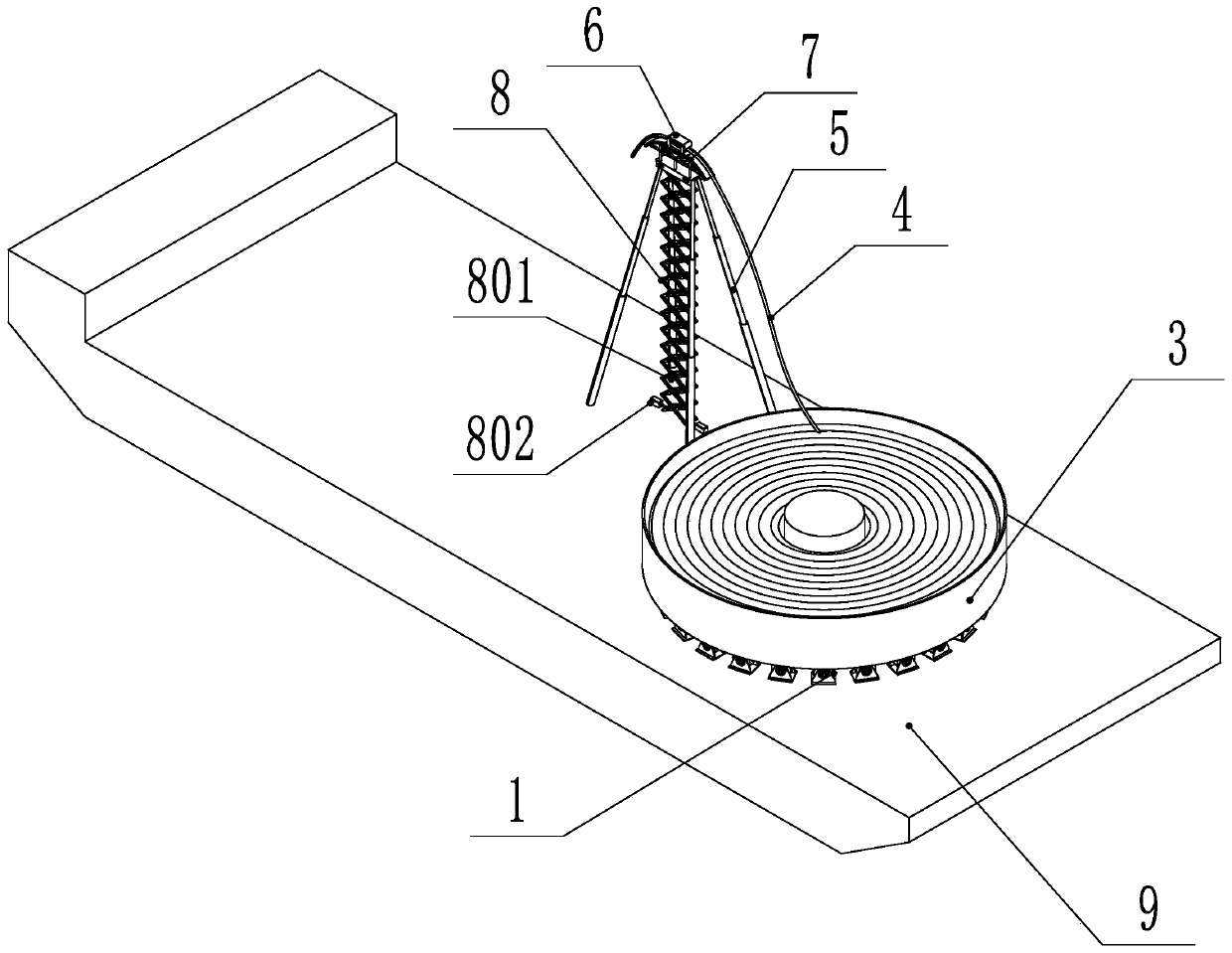
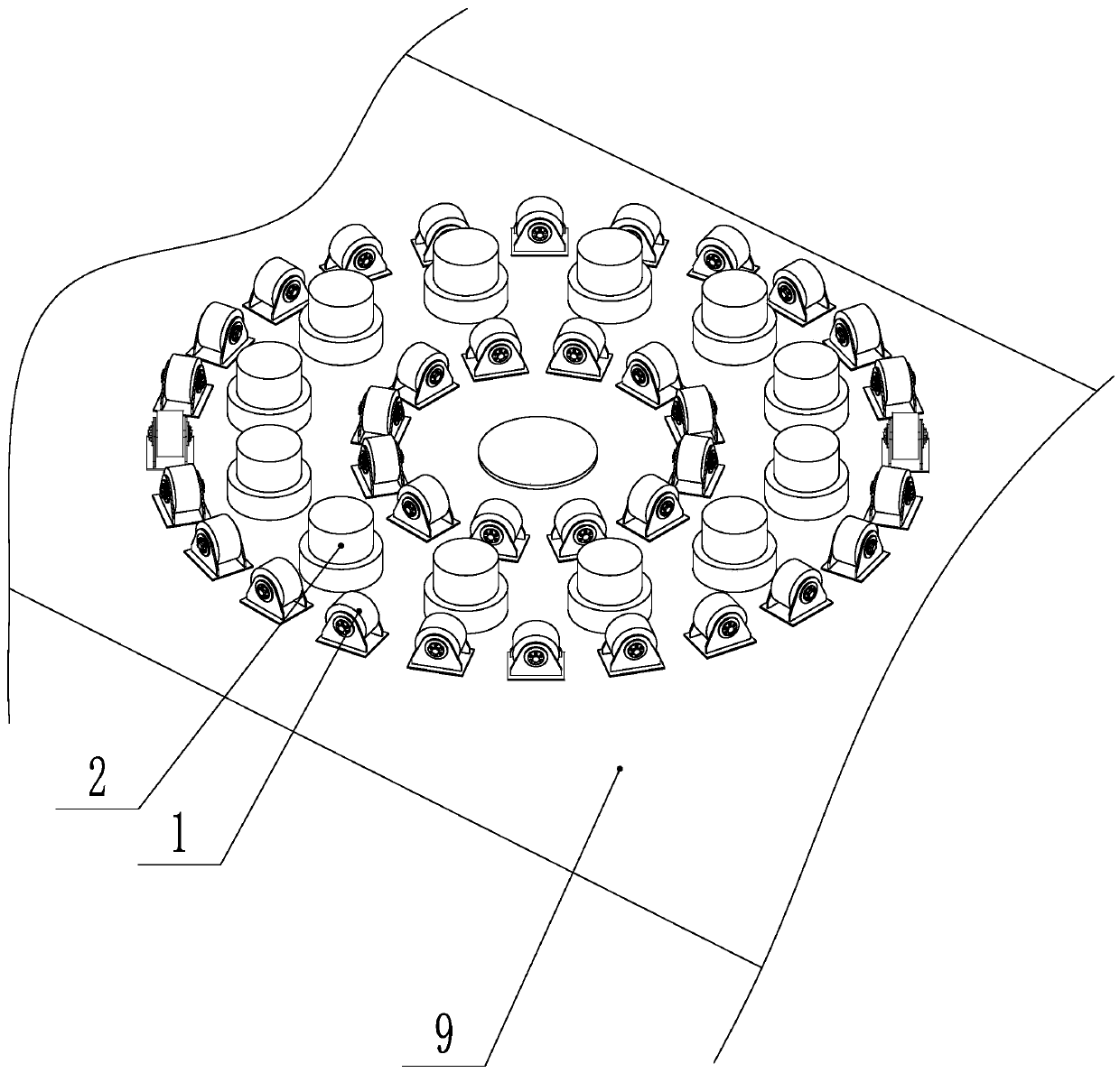
[0039] Such as Figure 1-5 As shown, the combined submarine cable untwisting system for various sections of submarine cable untwisting includes a submarine cable storage tray 3, 12 liftable load-bearing platforms 2, a liftable lifting tower 8, and is used to drive the tugboat 1 to rotate The submarine cable storage disk rotation drive device, the submarine cable bracket 7 arranged on the upper part of the lifting tower 8, the cable discharge tractor 6 for pulling the submarine cable 4, and the submarine cable storage disk rotation drive device and the cable discharge traction machine 6 are connected. The controller, the submarine cable storage disk rotation drive device, and the load-bearing platform 2 are set under the submarine cable storage disk 3; the 12 load-bearing platforms 2 and the submarine cable storage disk 3 are arranged...


PUM


Abstract

The invention discloses a combined type submarine cable back twisting system used for multi-section submarine cable back twisting and relates to a submarine cable back twisting system. The back twisting way of submarine cables is single and cannot be applied to submarine cables of different diameters. The combined type submarine cable back twisting system comprises a submarine cable reel, multipleload-bearing platforms capable of rising and falling, a lifting tower capable of rising and falling, a submarine cable reel rotation driving device used for driving towing wheels to rotate, a submarine cable bracket arranged on the upper portion of the lifting tower, a cable outlet traction machine used for dragging submarine cables, and a controller connected with the submarine cable reel rotation driving device and the cable outlet traction machine. The submarine cable reel rotation driving device and the load-bearing platforms are arranged under the submarine cable reel. The multiple load-bearing platforms and the submarine cable reel are arranged concentrically and circumferentially. According to the combined type submarine cable back twisting system, two manners of horizontal rotating back twisting and altitudinal back twisting can be achieved conveniently, the back twisting manners are switched conveniently, the different back twisting manners can be used according to the submarine cables of different sections, the operation is easy, and switching is convenient.

Description

technical field [0001] The invention relates to a submarine cable untwisting system, in particular to a combined submarine cable untwisting system used for untwisting submarine cables of various cross-sections. Background technique [0002] At present, after the completion of production and before laying construction, the submarine cable must be coiled in a circular submarine cable storage tray under the action of an external force in a manner similar to a steel wire rope. This winding method will have inherent damage to the armored submarine cable. Rotational stress, every time a coil is coiled, there will be an additional circular torsion, which requires a certain method to release the coiled circular stress one by one during the transfer and laying of the submarine cable, so as to prevent uneven or accumulated twisting. cause cable damage. [0003] At present, there are two main methods for submarine cable back twisting: [0004] high back twist [0005] Technical prin...

Claims


Application Information

Patent Timeline
Patent Type & Authority Patents(China)
IPC IPC(8): B65H49/20B65H49/18
Inventor 陈锡祥朱云祥段军闫循平彭维龙徐建良丁兆冈林晓波朱志刚郭华刘臻
Owner STATE GRID ZHEJIANG ELECTRIC POWER
Why Eureka
Try Eureka