
Self-adaptive steel truss girder gravity center and installation inclination angle change hoisting lifting appliance and construction method

A steel truss girder, self-adaptive technology, applied in the direction of bridges, bridge construction, transportation and packaging, etc., can solve the problems of uneven center of gravity, increase the cost of measures, etc., achieve the effect of reducing spreaders, reducing cost of measures, and simple construction technology

Pending Publication Date: 2018-07-13
四川路桥华东建设有限责任公司
View PDF0 Cites 1 Cited by
  • Summary
  • Abstract
  • Description
  • Claims
  • Application Information

AI Technical Summary

Problems solved by technology

[0005] Therefore, in order to solve the above-mentioned deficiencies, the present invention hereby provides a hoisting sling and construction method for changing the center of gravity of the self-adaptive steel truss girder and the installation inclination angle; it mainly solves the problem that the hoisting of large sections of the steel truss girder has different centers of gravity and requires multiple sets of slings to realize hoisting , thereby increasing the cost of the measure

Method used


Image

  • Self-adaptive steel truss girder gravity center and installation inclination angle change hoisting lifting appliance and construction method
  • Self-adaptive steel truss girder gravity center and installation inclination angle change hoisting lifting appliance and construction method
  • Self-adaptive steel truss girder gravity center and installation inclination angle change hoisting lifting appliance and construction method

Examples


Embodiment Construction

[0033] The following will be combined with Figure 1-Figure 12 The present invention is described in detail, and the technical solutions in the embodiments of the present invention are clearly and completely described. Apparently, the described embodiments are only some of the embodiments of the present invention, not all of them. Based on the embodiments of the present invention, all other embodiments obtained by persons of ordinary skill in the art without making creative efforts belong to the protection scope of the present invention.

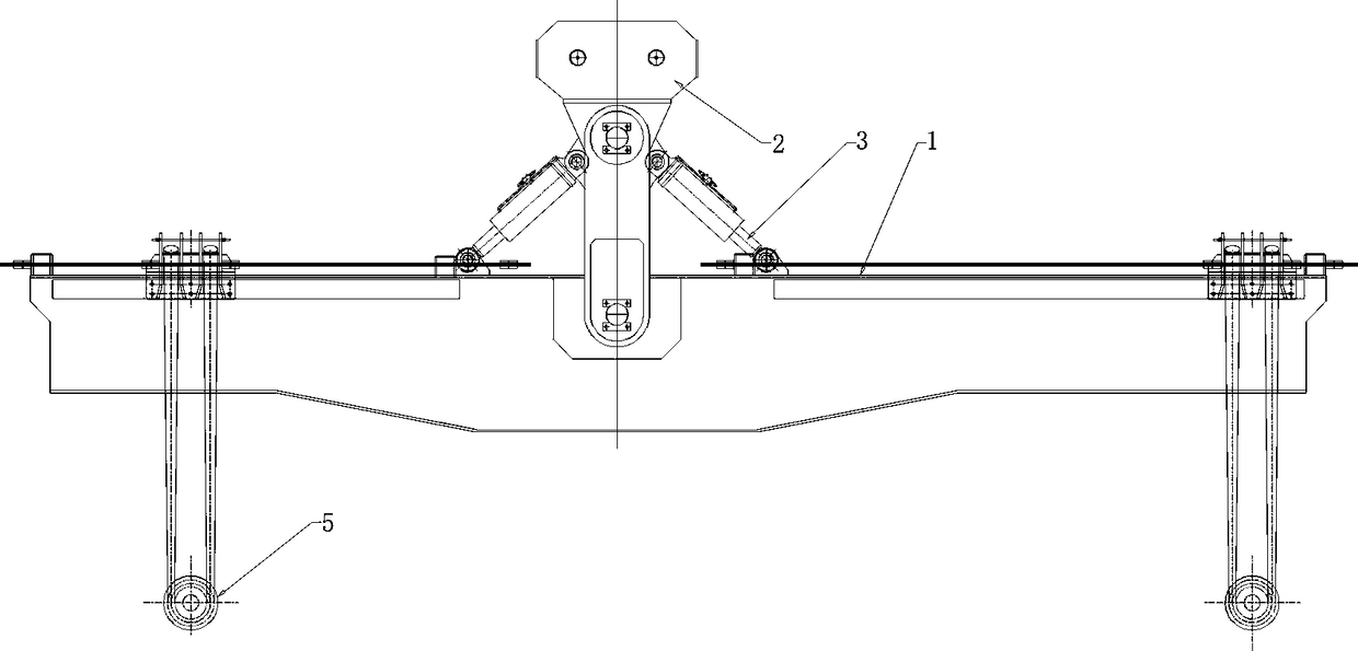
[0034] The present invention provides a kind of self-adaptive steel truss girder center of gravity, installation inclination angle change hoisting sling here through improvement, such as Figure 1-Figure 9 As shown, it can be implemented as follows; the main structure includes spreader main beam 1, movable pulley assembly 2, oil cylinder 3, fixed base 4, sling assembly 5, high-strength finish-rolled rebar A6, high-strength finish-rolled reba...


PUM


Abstract

The invention discloses a self-adaptive steel truss girder gravity center and installation inclination angle change hoisting lifting appliance and a construction method. The main structure comprises alifting appliance main beam, a movable pulley assembly, an oil cylinder, a fixed base, a suspender assembly, a high-strength finish rolling thread steel A, a high-strength finish rolling thread steelB, a high-strength finish rolling thread steel bar matching nut and a cotter pin; the lifting belt assembly is located on the lifting appliance main beam, and the movable pulley assembly is located on the lifting appliance main beam; the two sides of the movable pulley assembly are correspondingly provided with oil cylinders, the high-strength finish-rolled threaded steel A and the high-strengthfinish-rolled threaded steel B penetrate through the suspender assembly and the corresponding high-strength finish-rolled threaded steel rod matched nut correspondingly. According to the gravity center and the hoisting lifting appliance and the method, after being improved, the change of the center of gravity of the large-section hoisting of the structural object can be effectively applied, the lifting appliance is reduced, the measure cost is reduced, the construction process is simple and rapid, the installation difficulty is reduced, the total construction period is saved, and the measure cost is greatly reduced.

Description

technical field [0001] The invention relates to the construction field of a center-of-gravity spreader, in particular to an adjustable center-of-gravity lifter for hoisting a 650t steel truss girder and a construction method. Background technique [0002] As a basic construction with a long history, bridges are an important part of the transportation network and the improvement of the transportation industry. Especially in view of my country's vast territory and numerous waterways, bridges play an irreplaceable role in promoting national economic development and ensuring political stability. With the development of new materials, new bridges with steel structures as the main body are gradually being applied to engineering practice. my country, as a big country of bridges and steel, has a wider range of applications based on steel structure bridges, and more and more super-large and super-heavy components are hoisted. , which means that the component center of gravity and ins...

Claims


Application Information

Patent Timeline
Patent Type & Authority Applications(China)
IPC IPC(8): B66C13/08B66C13/16E01D21/00
CPCE01D21/00B66C13/085B66C13/16
Inventor 刘杰魏鹏飞卜鑫闵玉周康福黄赓宇邓勇李亮郭杰王磊顾航
Owner 四川路桥华东建设有限责任公司
Learn More