
Downhole automatic ball throwing device for oil field

A ball-throwing device and technology for oil field wells, applied in the direction of wellbore/well valve devices, wellbore/well components, production fluids, etc., can solve the problems of inability to meet the existing process requirements, low work efficiency, time-consuming and labor-intensive measures, etc. , to achieve the effect of reducing labor intensity and cost of measures, reasonable structure and convenient operation

Pending Publication Date: 2020-11-03
KARAMAY HONGDU
View PDF0 Cites 0 Cited by
  • Summary
  • Abstract
  • Description
  • Claims
  • Application Information

AI Technical Summary

Problems solved by technology

[0003] The present invention provides an automatic ball-throwing device in an oil field, which overcomes the above-mentioned deficiencies in the prior art, and can effectively solve the problem of layer change in the existing mechanical segmental control water-finding process. purpose, resulting in low work efficiency, time-consuming and labor-intensive measures, and high cost of measures, which can no longer meet the existing process requirements

Method used


Image

  • Downhole automatic ball throwing device for oil field
  • Downhole automatic ball throwing device for oil field
  • Downhole automatic ball throwing device for oil field

Examples


Embodiment Construction

[0018] The present invention is not limited by the following examples, and specific implementation methods can be determined according to the technical solutions of the present invention and actual conditions.

[0019] In the present invention, for the convenience of description, the description of the relative positional relationship of each component is based on the description attached to the description. figure 1 For example, the positional relationship of front, back, up, down, left, right, etc. is based on the attached figure 1 determined by the layout direction.

[0020] Below in conjunction with embodiment and accompanying drawing, the present invention will be further described:

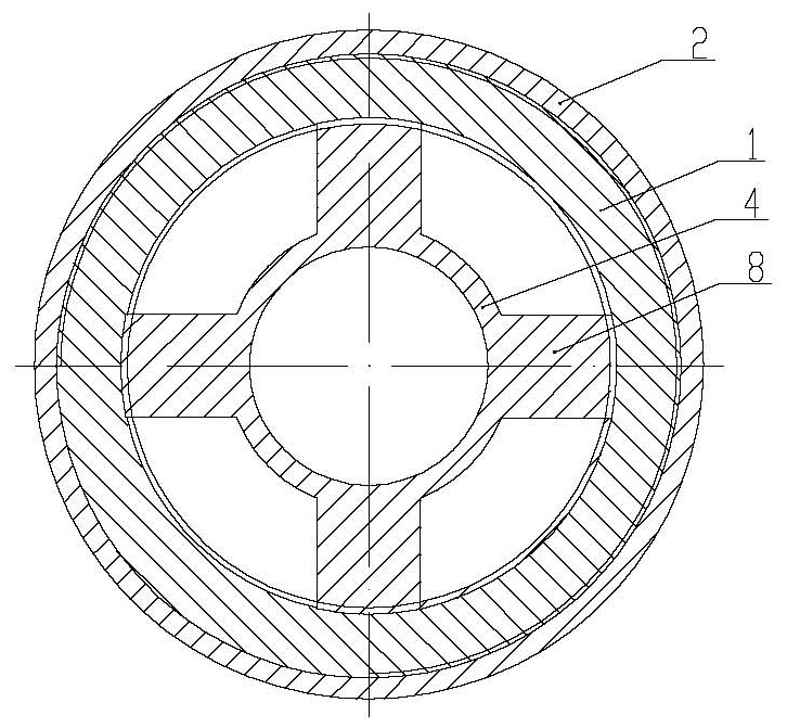
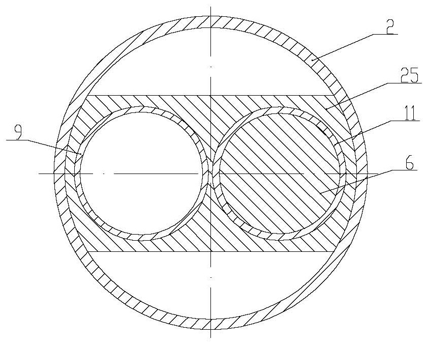
[0021] as attached figure 1 , 2 , 3, and 4, the oil field downhole automatic ball throwing device includes an upper joint 1, an outer cylinder 2, a lower joint 3, a positioning sleeve 4, a crankshaft 5, a trigger lever 6 and a trigger lever joint 7; the lower outer side of the upper joint...


PUM


Abstract

The invention relates to the technical field of oil field machinery, in particular to a downhole automatic ball throwing device for an oil field. The device comprises an upper connector, an outer barrel, a lower connector and a positioning sleeve, wherein the upper connector and the outer barrel are fixedly mounted together, the outer barrel and the lower connector are fixedly mounted together, and the positioning sleeve is located on the lower portion of an inner cavity of the upper connector; a ball storage barrel is fixedly mounted on the left portion of the inner cavity of the outer barrel, a bottom plug is fixedly mounted on the inner side of the lower end of the ball storage barrel, and a guide sleeve is fixedly mounted on the right portion of the inner cavity of the outer barrel; and corresponding ball holes are formed in the right side of the lower portion of the ball storage barrel and the left side of the lower portion of the guide sleeve respectively, and the lower end of acrankshaft penetrates through the positioning sleeve to be fixedly connected with the upper end of a trigger rod. The downhole automatic ball throwing device is reasonable and compact in structure andconvenient to use, well achieves the purpose of layer changing without lifting out a sucker rod, and has the advantages of being safe and reliable, operations are facilitated, work efficiency is improved, labor intensity and measure cost of operators are greatly reduced, and the requirements of an existing process can be well met.

Description

technical field [0001] The invention relates to the technical field of oilfield machinery, and relates to an automatic downhole ball throwing device for an oilfield. Background technique [0002] Since horizontal wells have a larger drainage area and higher recovery than conventional vertical wells, the number of horizontal wells has increased in recent years. The situation of water breakthrough has become prominent, leading to a further reduction in recovery, and even some wells have been flooded, and the produced fluid contains more than 95% water. Therefore, research and update of water discovery technology is a prerequisite for efficient production of horizontal wells. At present, in the horizontal well mechanical segmental control water search process generally adopted in China, the method of throwing balls is used to realize the opening of the suction layer and the closing of the suction layer. The purpose of layer change can only be achieved by throwing the oil rod a...

Claims


Application Information

Patent Timeline
Patent Type & Authority Applications(China)
IPC IPC(8): E21B34/14E21B43/14
CPCE21B34/14E21B43/14
Inventor 高伟王海峰张胜刘亮亮崔梅芹李嘉玮柯迪昕赵博闻别尔林·孜拉汗阿热依·哈尼
Owner KARAMAY HONGDU
Learn More