
Building prefabricated component hoisting and conveying equipment

A technology of prefabricated components and equipment, applied in the directions of transportation and packaging, load hanging components, cranes, etc., can solve the problems of not adapting to the needs of multi-directional operations, the prefabricated components are not tightly clamped, and the prefabricated components are falling, etc. Stable, to avoid falling, to ensure the effect of safe work

Inactive Publication Date: 2018-07-13
成都魔童童工业设计有限公司
View PDF0 Cites 7 Cited by
  • Summary
  • Abstract
  • Description
  • Claims
  • Application Information

AI Technical Summary

Problems solved by technology

However, the traditional lifting equipment has the disadvantages of non-rotatable angle and insufficient clamping of prefabricated components, resulting in the phenomenon that it is not suitable for multi-directional operations and prefabricated components fall

Method used


Image

  • Building prefabricated component hoisting and conveying equipment
  • Building prefabricated component hoisting and conveying equipment
  • Building prefabricated component hoisting and conveying equipment

Examples


Embodiment Construction

[0019] The following will clearly and completely describe the technical solutions in the embodiments of the present invention with reference to the accompanying drawings in the embodiments of the present invention. Obviously, the described embodiments are only some, not all, embodiments of the present invention.

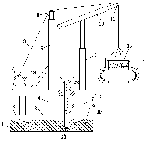
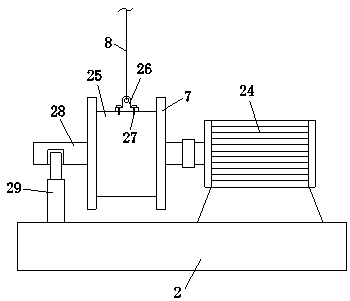
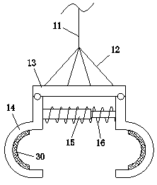
[0020] refer to Figure 1-3 , a prefabricated building component lifting equipment, comprising a base 1 arranged horizontally, a bearing seat 3 is provided at the center of the top surface of the base 1, a rotating shaft 4 is vertically provided inside the bearing seat 3, and a support plate 2 is horizontally provided at the top of the rotating shaft 4 The base 1 supports the rotating shaft 4 through the bearing seat 3, the rotating shaft 4 can rotate in the bearing seat 3, and the top of the rotating shaft 4 supports the support plate 2, and then supports other parts of the lifting equipment.

[0021] A rotating mechanism is provided between the top surface of the b...


PUM


Abstract

The invention relates to the technical field of hoisting and conveying equipment, in particular to building prefabricated component hoisting and conveying equipment. The building prefabricated component hoisting and conveying equipment comprises a horizontally-arranged base. A bearing block is arranged at the center position of the top face of the base. A rotation shaft is vertically arranged in the bearing block. A supporting plate is horizontally arranged at the top end of the rotation shaft. A rotation mechanism is arranged between the top face of the base and the bottom face of the supporting plate. A threaded hole is formed in one end of the supporting plate and internally provided with a stud. A positioning groove is formed in one end of the top face of the base. The bottom end of the stud is arranged in the positioning groove. A stand column is vertically arranged at the center position of the top face of the supporting plate. A first pulley is arranged at the top end of the stand column. An inclined rod is rotationally arranged at the top end of one side of the stand column. A first telescopic rod is vertically arranged at one end of the top face of the supporting plate. The top end of the first telescopic rod is fixedly connected with the bottom face of the inclined rod, and a second pulley is arranged at the other end of the inclined rod. The building prefabricated component hoisting and conveying equipment is simple in operation, convenient to use and capable of rotating to meet the multi-direction hoisting equipment; and prefabricated component clamping is stable, prefabricated component falling is avoided, and safety work is ensured.

Description

technical field [0001] The invention relates to the technical field of hoisting equipment, in particular to a hoisting equipment for building prefabricated components. Background technique [0002] In the construction process of construction projects, some components are prefabricated, and the use of these prefabricated components requires the use of lifting equipment. However, the traditional lifting equipment has the disadvantages of non-rotatable angle and loose clamping of prefabricated components, which leads to the phenomenon that it does not meet the needs of multi-directional operations and the prefabricated components fall. For this reason, we propose a kind of building prefabricated component hoisting equipment. Contents of the invention [0003] The purpose of the present invention is to solve the shortcomings in the prior art, and propose a kind of building prefabricated component lifting equipment. [0004] In order to achieve the above object, the present i...

Claims


Application Information

Patent Timeline
Patent Type & Authority Applications(China)
IPC IPC(8): B66C23/16B66C23/78B66C1/12B66C1/44
CPCB66C23/16B66C1/12B66C1/44B66C23/78
Inventor 朱梦佼
Owner 成都魔童童工业设计有限公司
Learn More