Pipe support frame

A technology of support frame and pipe frame, applied in the direction of pipe support, pipe/pipe joint/pipe fitting, mechanical equipment, etc., can solve the problems of small adaptability and cannot be adjusted according to needs, etc., to achieve the effect of convenient laying

Active Publication Date: 2018-07-13
张家港保税区金运通市政建筑工程有限公司
View PDF10 Cites 14 Cited by
  • Summary
  • Abstract
  • Description
  • Claims
  • Application Information

AI Technical Summary

Problems solved by technology

However, this pipe support frame is fixed and cannot be a

Method used


Image

  • Pipe support frame
  • Pipe support frame
  • Pipe support frame

Examples


specific Embodiment approach 1

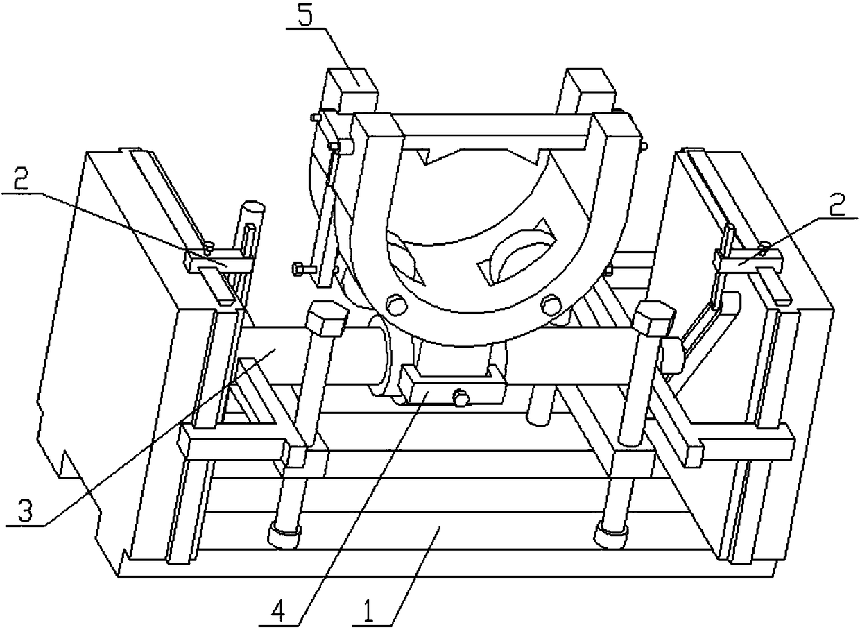
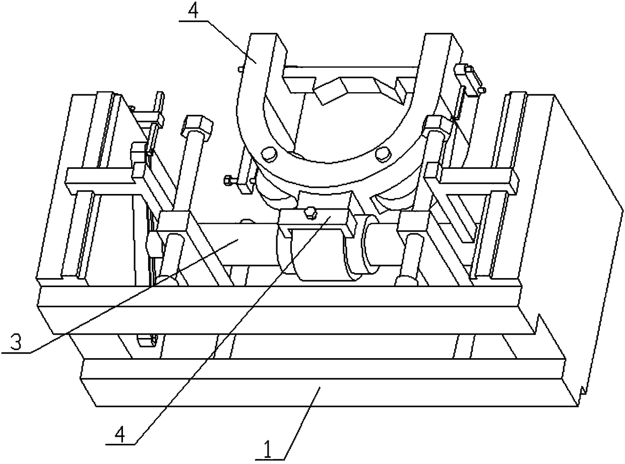
[0026] Combine below Figure 1-10 This embodiment is described. The present invention relates to the field of pipeline laying engineering, more specifically, a pipeline support frame, which includes a frame assembly 1, a groove bar assembly 2, a horizontal frame assembly 3, a positioning piece 4, and a pipe frame 5. The device supports The height and left and right positions of the pipeline can be adjusted, and the device can adapt to the laying of inclined pipelines at a certain angle to the ground, and the pipeline can be rotated on the device, which is convenient for the laying of pipelines that need to be connected by threads.

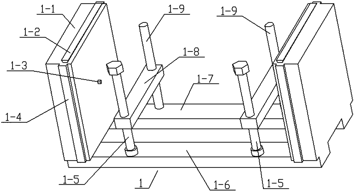
[0027] The frame assembly 1 includes a side plate 1-1, a trapezoidal convex strip 1-2, a cylindrical convex strip 1-3, a rectangular convex strip 1-4, a front bottom strip 1-6 and a rear bottom strip 1-7, the side There are two boards 1-1, a rear bottom strip 1-7 is fixedly connected between the rear ends of the lower ends of the two side boards 1-...


PUM


Abstract

The invention relates to the field of pipe pavement engineering, in particular to a pipe support frame. The pipe support frame comprises a frame module, a groove rod module, a transverse frame module,a positioning piece and a pipe frame; the height and the left-right position of a support pipe in the device can be adjusted; the device can adapt to pavement of an inclined pipe forming a certain angle with the ground; and the pipe can be rotated on the device to achieve pavement of the pipe needing to be connected through threads. The frame module comprises side plates, trapezoidal convex bars,cylindrical convexes, rectangular convex bars, a front bottom batten and a back bottom batten; the two side plates are provided; the back bottom batten is fixedly connected between the back ends of the lower ends of the two side plates; the front bottom batten is fixedly connected between the front ends of the lower ends of the two side plates; the rectangular convex bars are arranged on the front and back end surfaces of the two side plates; the side plates are arranged on the upper end surfaces of the two side plates; and the cylindrical convex is fixedly connected to the middle positions of opposite surfaces of the two side plates.

Description

technical field [0001] The invention relates to the field of pipeline laying engineering, in particular to a pipeline support frame. Background technique [0002] The application number is CN201620074155.4 for an oil pipeline support frame. The utility model discloses an oil pipeline support frame, which relates to the field of oil field machinery and equipment. The connection is fixed by rivets. There are semi-cylindrical holes of the same size at the bottom of the top frame and the top of the bottom frame. A layer of inner liner is bonded to the inner wall of the two half-cylindrical holes. Two triangular holes are symmetrically arranged at the bottom of the bottom frame. There are several pre-embedded rods, and a pre-embedded sheet is arranged at the bottom of each pre-embedded rod. The inner liner made of high-temperature-resistant rubber has an interference fit with the oil pipeline, and the external rivet is fixedly connected, which can effectively fix the oil pipelin...

Claims


Application Information

Patent Timeline
IPC IPC(8): F16L3/02
CPCF16L3/02
Inventor 邓银
Owner 张家港保税区金运通市政建筑工程有限公司
Why Eureka
Try Eureka