
LED lamp

A technology of LED lamps and LED circuit boards, applied in lighting and heating equipment, instruments, mechanical equipment, etc., can solve the problems of unsuitable flat LED lamps, LED lamp brightness enhancement, and unsuitable LED lamps, etc., to achieve the utilization rate of light High, uniform lighting, small footprint effect

Pending Publication Date: 2018-07-13
中科同德(北京)生态科技有限公司
View PDF0 Cites 0 Cited by
  • Summary
  • Abstract
  • Description
  • Claims
  • Application Information

AI Technical Summary

Problems solved by technology

Traditional LED lights are prone to problems such as through spots and uneven lighting. The general solution to this problem is to increase the number of LED lights. However, the above solutions will greatly increase the brightness of LED lights, which is not suitable for the production of night sleep. There is another solution is to place the light point of the LED lamp outside the light guide structure, but the above solution is based on the premise that there is sufficient space between the upper cover of the LED lamp and the LED circuit board, and is not applicable It is suitable for the production of flat LED lights that are often used in small-sized houses, that is, LED lights with only a small space between the upper cover of the LED light and the LED circuit board

Method used


Image

  • LED lamp
  • LED lamp
  • LED lamp

Examples


Embodiment 1

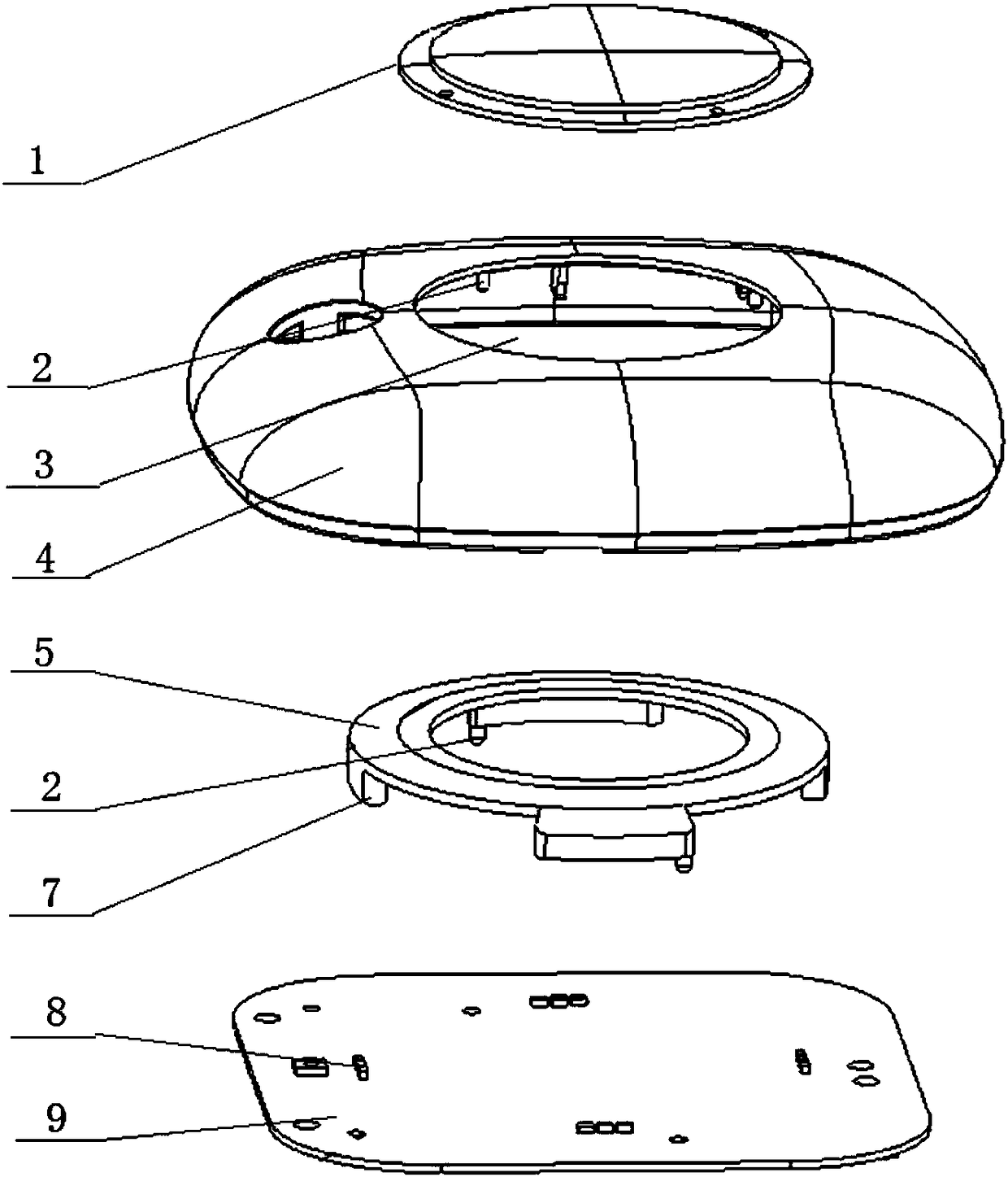
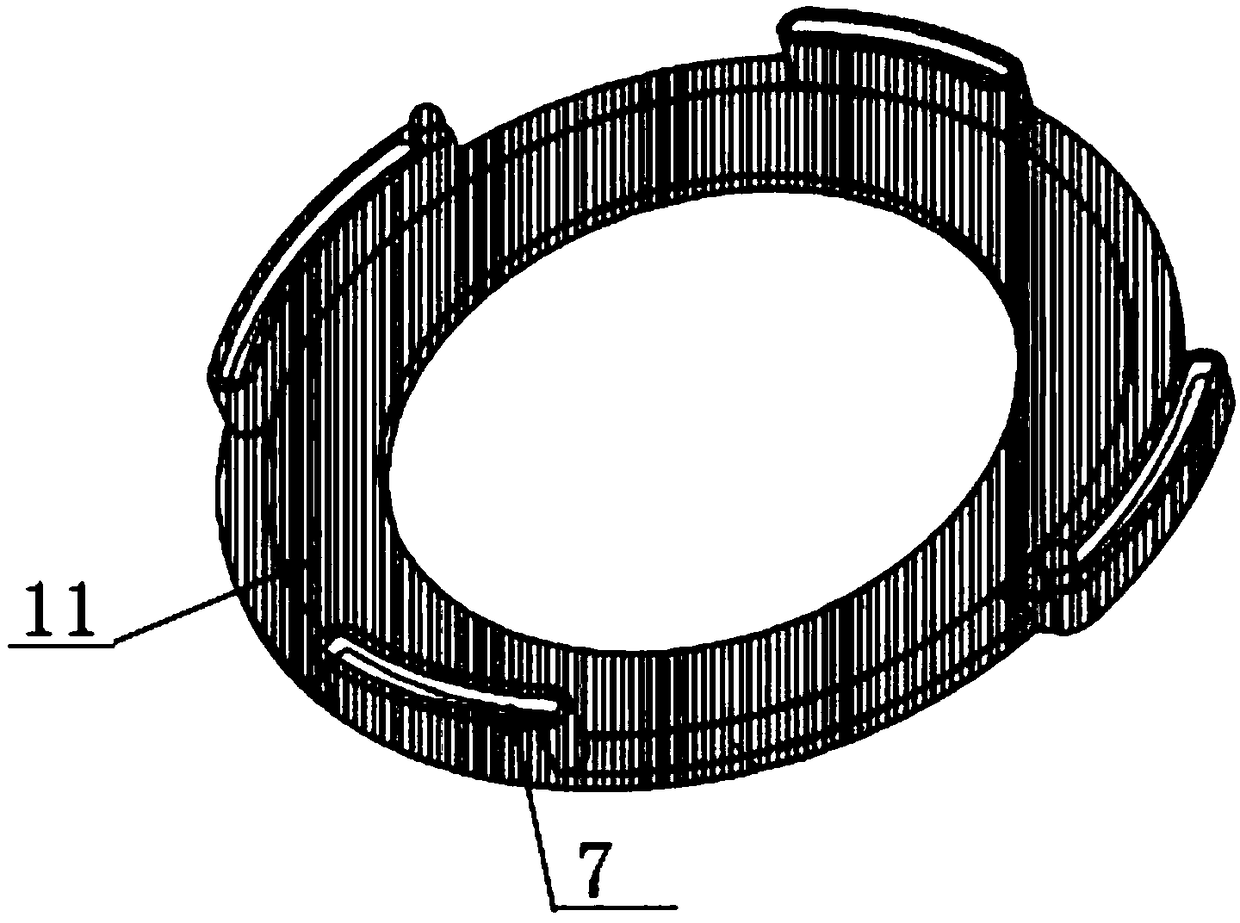
[0041] In this embodiment, the light guide part 12 includes a first reflective plate 10 and a second reflective plate 11 oppositely arranged for light reflection, so that the light from the LED lamp point 8 exits the light guide part 12 upwards relative to the horizontal plane;

[0042] Preferably, the section lines of the first reflective plate 10 and the second reflective plate 11 are arranged in parallel.

[0043] The light guide part 12 of the above-mentioned structure makes the light of the LED lamp point 8 irradiate upwards relative to the horizontal surface, which improves the utilization rate of the light. It is used to estimate the light irradiation range of the LED lamp, or adjust the structure of the light guide body 5 to change the light path of the light from the LED lamp point 8 .

Embodiment 2

[0045] In this embodiment, the upper side of the light guide part 12 is provided with a light-transmitting plate 6 for emitting light from the LED lamp point 8, and the two ends of the light-transmitting plate 6 are connected to the first reflector 10 and the second reflector 11 respectively. Phase-tight connection. Specifically, the transparent plate 6 is arranged horizontally.

[0046] The above arrangement makes the light guide body 5 in a sealed state, preventing dust from entering the light guide body 5 and affecting the reflection and divergence effect of the light guide body 5 on the light from the LED lamp spot 8 .

Embodiment 3

[0048] In this embodiment, the light guide body 5 is made of acrylic material. The light incident part 7 and the light guide part 12 are formed by spraying white paint to have a reflective effect. The paints used in the present invention are all high-gloss paints to enhance the reflection of light from the LED light spot 8 . The light-transmitting plate 6 is not sprayed with paint and is in a transparent state.

[0049] Acrylic has good light transmittance and is not brittle. Even if it is broken, it will not form sharp fragments, thus avoiding personnel scratch accidents caused by light guide body 5 being broken or broken after being broken. At the same time, it also has better Excellent high-temperature performance and processing performance, thereby ensuring that the light guide body 5 can be sleeved outside the heat-generating LED light point 8, and white paint can be sprayed on the light guide body 5 to improve light utilization and reflect light.


PUM


Abstract

The invention relates to an LED lamp which comprises an LED circuit board. LED lamp points are arranged on the LED circuit board, and a light guide body is also arranged on the LED circuit board. Thelight guide body comprises a light input part which is vertically fixed to the LED circuit board and covers the periphery of the LED lamp points, and a light guide part which inclines upward relatively to the horizontal plane is arranged on the upper side of the light input part. The light guide part communicates through the side part to form a circular ring structure, and the light of the LED lamp points is shot from the transparent place of the upper side of the light guide part. The light of the LED lamp points are reflected and diverged through the light guide body, so that a point-shapedlight source is converted to a strip-shaped light source, point appearance of the LED lamp is avoided, the light of the LED lamp is more uniform, and therefore the lighting effect of the LED lamp is improved.

Description

technical field [0001] The invention relates to an LED lamp. Background technique [0002] With the advancement of technology in related fields of household appliances, the public has higher and higher requirements for household appliances, such as LED lights, whose lighting effects have received more and more attention. Traditional LED lights are prone to problems such as through spots and uneven lighting. The general solution to this problem is to increase the number of LED lights. However, the above solutions will greatly increase the brightness of LED lights, which is not suitable for the production of night sleep. There is another solution is to place the light point of the LED lamp outside the light guide structure, but the above solution is based on the premise that there is sufficient space between the upper cover of the LED lamp and the LED circuit board, and is not applicable Flat LED lamps are mostly used in the production of small-sized houses, that is, LED lamp...

Claims


Application Information

Patent Timeline
IPC IPC(8): F21S8/00F21V8/00F21V7/05F21V19/00F21Y115/10
CPCF21S8/00F21V7/05F21V19/0055F21V2200/20
Inventor 徐广勇冯启源王禹稼马建伟廉季平孙熙航贾永超
Owner 中科同德(北京)生态科技有限公司
Learn More