Flow feature test equipment for fire extinguishing system pipe network

A technology of fire extinguishing system and experimental equipment, which is applied in the field of experimental equipment for the flow characteristics of the fire extinguishing system pipe network, can solve the problems of lack of flow characteristics of the fire extinguishing system pipe network, and achieve the effect of accurate description

Pending Publication Date: 2018-07-13
UNIV OF SCI & TECH OF CHINA +1
View PDF0 Cites 0 Cited by
  • Summary
  • Abstract
  • Description
  • Claims
  • Application Information

AI Technical Summary

Problems solved by technology

The present invention can solve the problem of the current lack of experimental equipment for the flow characteristics of the fire extinguishing system pipe network

Method used


Image

  • Flow feature test equipment for fire extinguishing system pipe network

Examples


Embodiment Construction

[0023] The present invention will be further described below through implementation examples in conjunction with the accompanying drawings, but the implementation scope of the present invention is not limited to this arrangement.

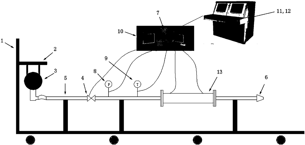
[0024] Such as figure 1 As shown, a kind of fire extinguishing system pipe network flow characteristics experimental equipment of the present invention includes an experimental bench 1, a fire extinguisher hanger 2, a fire extinguisher 3, a solenoid valve 4, a delivery pipeline 5, a terminal nozzle 6, a test interface 7, Pressure sensor 8, temperature sensor 9, signal conditioning and data acquisition module 10, industrial computer 11, console 12, and flow field visualization tomography analysis unit 13, the above-mentioned parts are connected to form a unit through mechanical connections, electrical cables and transportation pipelines Laboratory equipment.

[0025] figure 1 A schematic structural diagram of an experimental equipment for the flow ...


PUM


Abstract

The invention discloses flow feature test equipment for a fire extinguishing system pipe network. The equipment comprises a test rack, a fire extinguisher hanging rack, a fire extinguisher, an electromagnetic valve, a conveying pipeline, a tail-end nozzle, a test interface, a pressure sensor, a temperature sensor, a signal conditioning and data collecting module, an industrial control computer, acontrol panel and a flow field visualization chromatographic analysis unit. Compared with the prior art, the equipment has the advantages that the equipment can acquire the flowing and conveying information of a fire extinguishing agent in a pipeline system, confirm the influence of various pipeline parts on a flow field and provide technical support for the pipe network design of a novel fire extinguishing system.

Description

technical field [0001] The invention relates to the technical field of fire extinguishing system pipe network design, in particular to an experimental device for the flow characteristics of the fire extinguishing system pipe network. Background technique [0002] The flow characteristics of the fire extinguishing pipeline are related to the effectiveness of the fire extinguishing system. The current design of the fire extinguishing system is based on relevant fitting formulas measured by previous international experiments, including the calculation of parameters such as flow, pressure, and injection time in the fire extinguishing system pipeline. It should be pointed out that these fitting formulas are only obtained based on the flow parameters of the fire extinguishing agent under specific experimental conditions, and the flow rate and other parameters given are all constant, which cannot accurately reflect the real unsteady injection process of the fire extinguishing agent...

Claims


Application Information

Patent Timeline
Patent Type & Authority Applications(China)
IPC IPC(8): G01M10/00
CPCG01M10/00
Inventor 陆松曹承阳赵建华张和平刘鑫张立尧
Owner UNIV OF SCI & TECH OF CHINA
Why Eureka
Try Eureka