Zoom lens and imaging apparatus

A zoom lens and lens group technology, which is applied in the field of zoom lenses and camera devices, can solve problems such as large lens diameters, achieve high optical performance, and achieve miniaturization and light weight effects

Active Publication Date: 2018-07-13
FUJIFILM CORP
View PDF6 Cites 4 Cited by
  • Summary
  • Abstract
  • Description
  • Claims
  • Application Information

AI Technical Summary

Problems solved by technology

The lens system described in Patent Document 2 also has a large diameter of the front lens, so it cannot be said that miniaturization is sufficient.

Method used


Image

  • Zoom lens and imaging apparatus
  • Zoom lens and imaging apparatus
  • Zoom lens and imaging apparatus

Examples


Embodiment 1

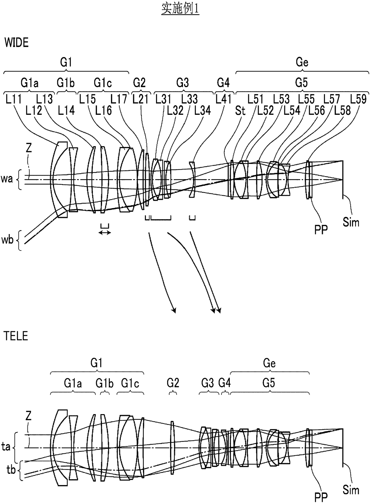
[0128] The lens structure of the zoom lens of embodiment 1 is as figure 1 As shown, the illustration method is the same as above, so a part of repeated description is omitted here. The zoom lens of Example 1 includes, in order from the object side, a first lens group G1 having positive refractive power, a second lens group G2 having positive refractive power, a third lens group G3 having negative refractive power, and a fourth lens group G4 having negative refractive power And the fifth lens group G5 with positive refractive power. The intervals between these five lens groups in the optical axis direction from adjacent groups change when the magnification is changed. The moving lens groups are the second lens group G2, the third lens group G3, and the fourth lens group G4, and the final lens group Ge is the fifth lens group G5.

[0129] The first lens group G1 includes, in order from the object side, a first lens group front group G1a having a negative refractive power, a fi...

Embodiment 2

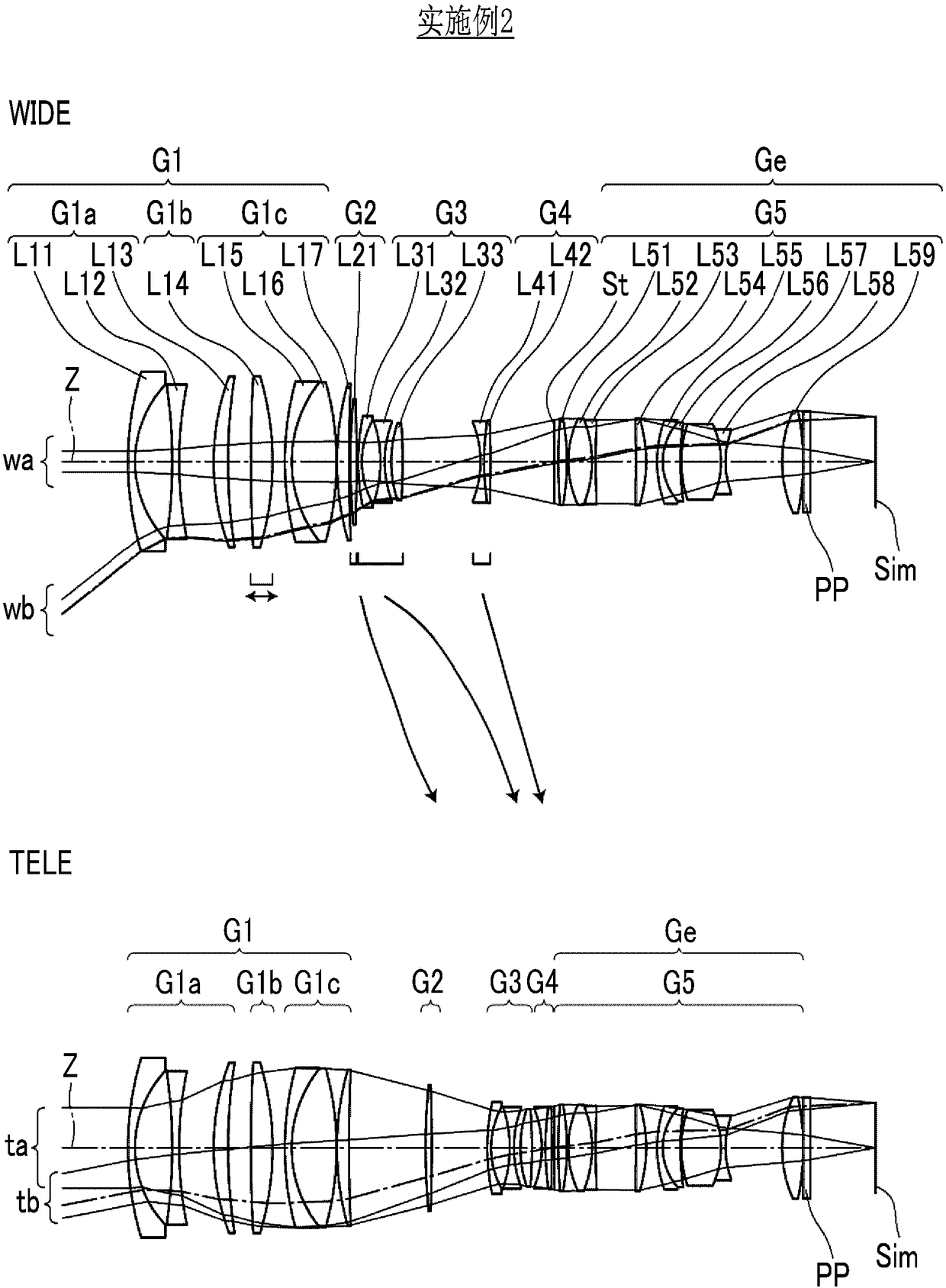
[0144] The lens structure and optical path of the zoom lens of embodiment 2 are shown in figure 2 middle. The group structure of the zoom lens of Example 2, the sign of the refractive power of each lens group, the lens groups that move when changing magnification, and the lens groups that move when focusing are the same as those of Example 1. The front group G1a of the first lens group includes three lenses of lenses L11 to L13 in order from the object side, the group G1b of the first lens group includes one lens of lens L14, and the rear group G1c of the first lens group includes lens L15 in order from the object side ~ L17 these 3 lenses. The second lens group G2 includes one lens of the lens L21. The third lens group G3 includes three lenses of lens L31 to lens L33 in this order from the object side. The fourth lens group G4 includes two lenses of lenses L41 to L42 in this order from the object side. The fifth lens group G5 includes an aperture stop St and nine lenses ...

Embodiment 3

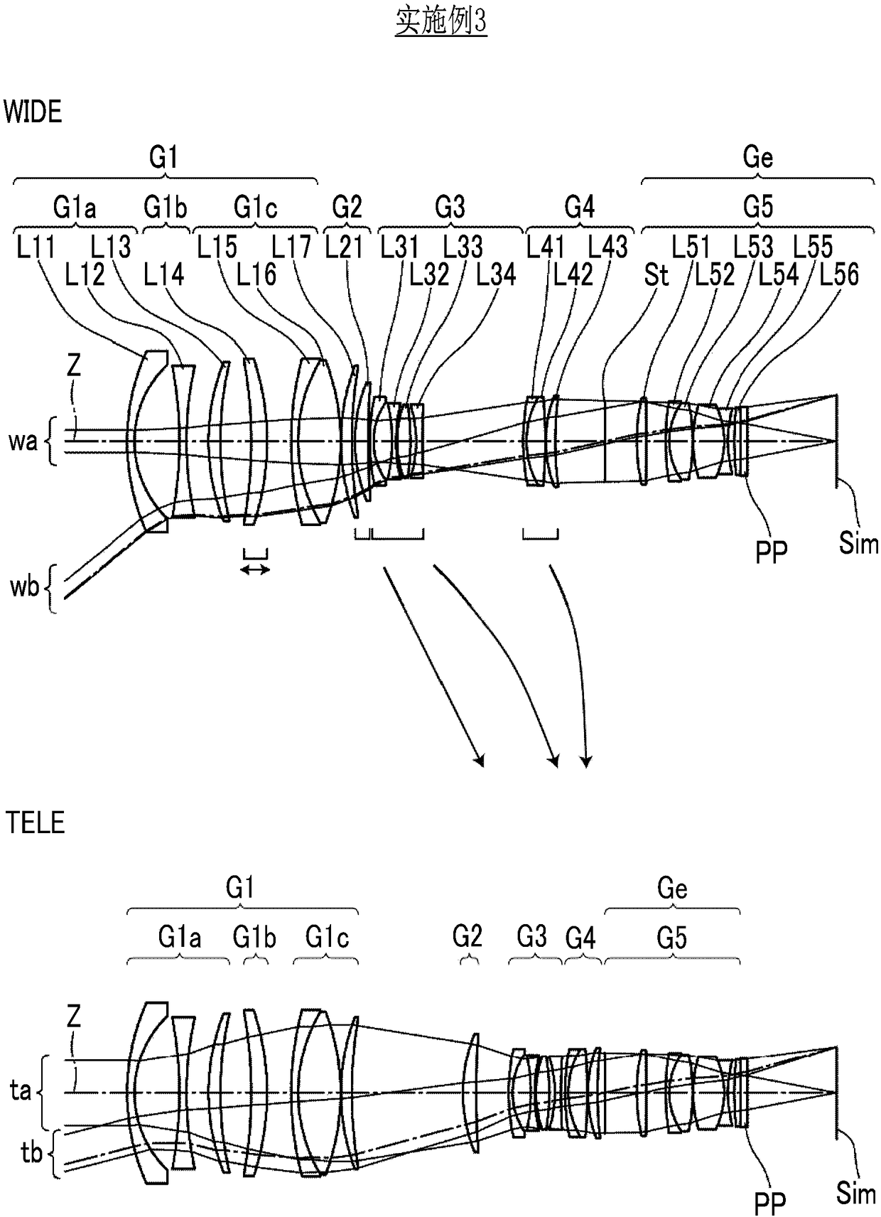
[0153] The lens structure and optical path of the zoom lens of embodiment 3 are shown in image 3 middle. The zoom lens of Example 3 includes, in order from the object side, a first lens group G1 having positive refractive power, a second lens group G2 having positive refractive power, a third lens group G3 having negative refractive power, and a fourth lens group G4 having positive refractive power And the fifth lens group G5 with positive refractive power. The first lens group G1 includes a first lens group front group G1a, a first lens group middle group G1b, and a first lens group rear group G1c in order from the object side. The lens groups that move during zooming and the lens groups that move during focusing in the zoom lens of Example 3 are the same as those of Example 1.

[0154] The front group G1a of the first lens group includes three lenses of lenses L11 to L13 in order from the object side, the group G1b of the first lens group includes one lens of lens L14, an...


PUM


Abstract

The present invention provides a zoom lens, for which reduction in size and weight is achieved while wide angle is achieved and which has high optical performance throughout the entire zoom range, andan imaging apparatus comprising the zoom lens. The zoom lens consists of, in order from the object side, a first lens group (G1) that has a positive refractive power and remains stationary during zooming, a plurality of movable lens groups that move during zooming, and a final lens group (Ge) that has a positive refractive power and remains stationary during zooming. The first lens group (G1) consists of, in order from the object side, a first lens group front group (G1a) that has a negative refractive power and remains stationary during focusing, a first lens group intermediate group (G1b) that has a positive refractive power and moves during focusing, and a first lens group rear group (G1c) that has a positive refractive power. The first lens group front group (G1a) has, successively inorder from a position closest to the object side, a negative meniscus lens that is concave toward the image side and a negative lens. Conditional Expression is satisfied, 1.84<Naven, where Naven is an average value of refractive indices of negative lenses in the first lens group front group (G1a).

Description

technical field [0001] The present invention relates to a zoom lens suitable for electronic cameras such as movie cameras, broadcast cameras, digital cameras, video cameras, and surveillance cameras, and an imaging device equipped with the zoom lens. Background technique [0002] Conventionally, a zoom lens having a 4-group structure or a 5-group structure has been used as a lens system of a camera that can be used in the above-mentioned fields. Movie cameras and broadcast cameras do not like changes in the total length of the lens system due to zooming and changes in the angle of view based on focusing. Therefore, when zooming, the lens group closest to the object side of the zoom lens is the first lens group. It is often set to be stationary, and the lens in the first lens group is moved to focus at the time of focusing. As such zoom lenses, zoom lenses described in Patent Document 1 and Patent Document 2 below are known, for example. [0003] Patent Document 1: Japanese...

Claims


Application Information

Patent Timeline
Patent Type & Authority Applications(China)
IPC IPC(8): G02B15/167
CPCG02B15/167G02B15/177G02B15/20G02B15/144109G02B15/145119G02B15/145127
Inventor 米泽贤田中琢也
Owner FUJIFILM CORP
Why Eureka
Try Eureka