Ventilation and heat dissipation method for temperature controllers

A technology for ventilation and heat dissipation, temperature controller, applied in the direction of thermal switch parts, electrical components, electric switches, etc., can solve the problems of difficult to replace, difficult to dissipate, damage to the temperature controller, etc., to improve efficiency, avoid easy damage, Ease of installation

Inactive Publication Date: 2018-07-13
HEFEI SHUSHI IND & TRADE CO LTD
View PDF5 Cites 2 Cited by
  • Summary
  • Abstract
  • Description
  • Claims
  • Application Information

AI Technical Summary

Problems solved by technology

[0003] The technical problem to be solved by the present invention is that the existing temperature controller, as a part installed inside the electrical appliance, is usually fixed inside the electrical appliance by welding or other means, and it is difficult to replace if it is damaged. At the same time, the temperature controller Located inside the electrical appliance, the heat generated by the electrical appliance and itself is difficult to dissipate, which can easily lead to damage to the thermostat itself. It is conducive to the replacement of the temperature controller at any time without replacing the electrical appliances; and it can cool down and dissipate heat around the temperature controller at any time to improve the efficiency of heat dissipation, thereby improving the quality of use of the temperature controller itself and avoiding long-term excessive temperature and easy damage

Method used


Image

  • Ventilation and heat dissipation method for temperature controllers

Examples


Embodiment

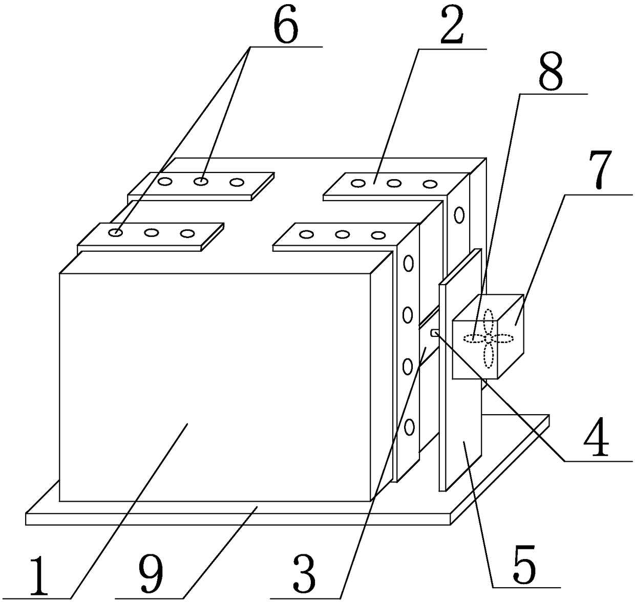
[0021] Such as figure 1 As shown, a method for ventilation and heat dissipation of a temperature controller in the present invention includes the following steps: 1) installing the temperature controller inside the electrical appliance, the temperature controller includes a temperature controller body 1, the left and right sides of the temperature controller body 1 There are two fixed groove plates 2 arranged in parallel at each end, the end of the temperature controller body 1 is embedded in the groove of the fixed groove plate 2, the inner wall of the fixed groove plate 2 and the upper surface of the temperature controller body 1 Slidingly connected with the lower surface, two fixed groove plates 2 arranged in parallel can move relatively along the surface of the temperature controller body 1 and the distance between them can be adjusted; the two fixed groove plates 2 are stretched The plate 3 is connected, the telescopic plate 3 is vertically connected with a connecting rod...


PUM


Abstract

The invention discloses a ventilation and heat dissipation method for temperature controllers. The ventilation and heat dissipation method includes steps of 1), mounting the temperature controllers inside electric appliances; 2), starting air blowing devices and driving expansion plates to be elongated and shortened back and forth. The temperature controllers comprise temperature controller bodies. Four fixing groove plates are arranged at two ends of each temperature controller body, and the inner walls of the fixing groove plates are slidably connected with the temperature controller bodies;every two corresponding fixing groove plates are connected with each other by the corresponding expansion plate, connecting rods are perpendicularly connected onto the expansion plates, support heatdissipation plates are connected with the ends of the connecting rods, heat dissipation holes are uniformly formed in the fixing groove plates, openings are formed in the support heat dissipation plates and are provided with heat dissipation tanks, and the air blowing devices are arranged in the heat dissipation tanks. The ventilation and heat dissipation method has the advantages that the ventilation and heat dissipation method can bring convenience for mounting the temperature controllers inside the electric appliances and is favorable for replacing the temperature controllers at any time without replacement of the electric appliances; the peripheries of the temperature controllers can be cooled at any time, heat can be dissipated for the peripheries of the temperature controllers at anytime, the heat dissipation efficiency can be improved, accordingly, the use quality of the temperature controllers can be improved, and temperature controllers can be prevented from being vulnerableto damage due to long-term excessively high temperatures.

Description

technical field [0001] The invention relates to a temperature controller, in particular to a ventilation and heat dissipation method for the temperature controller. Background technique [0002] A thermostat is a periodic temperature sensitive controller that maintains the temperature between two specified values ​​under normal operating conditions. And there may be a device for setting by the user. It is an automatic temperature controller mainly composed of a temperature sensing element and a control circuit. It is characterized in that it can determine whether the thyristor [SCR] The conduction angle and the state of on or off. It has simple circuit and long service life. The temperature control of the electric heating pan can increase the service life of the electric heating pan by 3 to 10 times, and the water temperature can be adjusted arbitrarily at 25 to 45°C when used in the electric heating shower to control the temperature, which can save energy by up to 60%. ...

Claims


Application Information

Patent Timeline
Patent Type & Authority Applications(China)
IPC IPC(8): H01H37/04H01H9/52
CPCH01H37/04H01H9/52
Inventor 黄浩郭伟郭元汪鹏许飞章波
Owner HEFEI SHUSHI IND & TRADE CO LTD
Why Eureka
Try Eureka