Permanent magnet motor stator and rotor assembling device and method

A permanent magnet motor, stator and rotor technology, applied in the direction of centering/balancing rotors, etc., can solve the problems that the assembly technology cannot meet the centering requirements, cannot ensure accurate centering and positioning, cannot accurately guide and adjust, and achieves compact structure. The effect of preventing winding damage and tilting

Active Publication Date: 2018-07-13
CSR ZHUZHOU ELECTRIC CO LTD
View PDF7 Cites 13 Cited by
  • Summary
  • Abstract
  • Description
  • Claims
  • Application Information

AI Technical Summary

Problems solved by technology

[0006] The combined assembly tooling described above can mostly solve the corresponding problems of stator and rotor assembly, but there are still the following difficulties in the combined assembly of stator and rotor with compact motor structure, one-sided weight of the rotor and in a narrow assembly space: 1. Accurate centering and positioning cannot be guaranteed, and the rotor will be subjected to a magnetic pull biased to one side, which is unfavorable for assembly
2. Generally, the diameter of the external guide hole is small, and the design of the guide tooling cannot determine the position of the rotor due to mutual attraction during the assembly process, which cannot be accurately guided and adjusted.
3. For the combination of stator and rotor with compact motor structure, one-sided weight of the rotor and in a narrow assembly space, the existing assembly technology cannot meet the alignment requirements

Method used


Image

  • Permanent magnet motor stator and rotor assembling device and method
  • Permanent magnet motor stator and rotor assembling device and method
  • Permanent magnet motor stator and rotor assembling device and method

Examples


Embodiment Construction

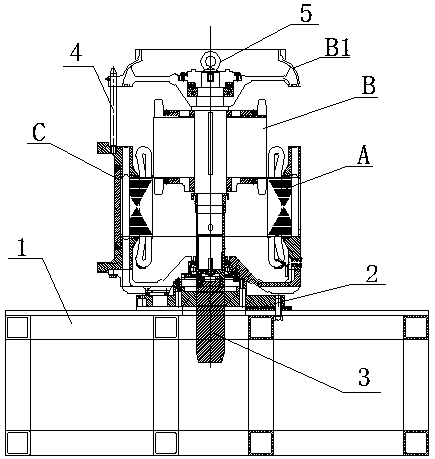
[0030] Attached below Figure 1~4 Embodiments of the present invention are described in detail.

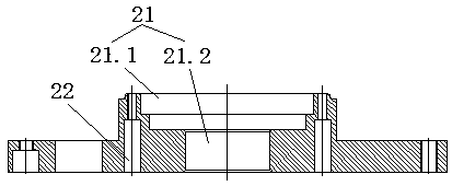
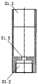
[0031] The permanent magnet motor stator and rotor assembly device is characterized in that it includes an assembly table 1 for supporting the assembly, a positioning plate 2 and a guide sleeve 3, the positioning plate 2 is provided with a guide hole 21, and the positioning plate 2 is fixed on the On the assembly platform 1, the guide sleeve 3 is detachably connected to the rotating shaft transmission end of the rotor B in the axial direction, and the stator A is detachably mounted on the positioning plate 2 and aligned coaxially with the guide hole 21, and the rotor B is combined with the stator A. During the assembly process, the guide sleeve 3 and the guide hole 21 guide and cooperate to pass through the positioning plate 2 and extend into the assembly platform 1 .

[0032] Such as figure 1 As shown, the assembly table 1 has a certain height, and the positioning plate 2 is fi...


PUM


Abstract

A permanent magnet motor stator assembling device is characterized by comprising an assembling platform for supporting, a positioning plate and a guide bushing, wherein the positioning plate is provided with a guide hole and is fixed to the assembling platform, the guide bushing is axially detachably connected with a revolving shaft drive end of a rotor, and a stator is detachably mounted on the positioning plate and aligned to the guide hole coaxially; in the assembling process of the stator and rotor, the guide bushing matches with the guide hole in a guided way and runs through the positioning plate to extend to the assembling platform. In application of the permanent magnet motor stator and rotor assembling device, accurate centering positioning and guiding of the stator and the rotorduring assembling is guaranteed, centering requirements of assembling of the stator and the rotor are met, the stator and the rotor are assembled in a reliable, safe and effective way without any damage to winding, and quality and precision of assembling of the stator and the rotor are guaranteed. The invention further relates to a permanent magnet motor stator and rotor assembling method.

Description

technical field [0001] The invention relates to a stator-rotor combination device and method for a permanent magnet motor, which is used for fast combined rotation of the rotor and the stator in the permanent magnet motor, and belongs to the technical field of motor manufacturing. Background technique [0002] Due to its high power factor and high efficiency, permanent magnet motors have gradually replaced the most commonly used AC asynchronous motors in many occasions. The difficulty in the assembly of the stator and rotor of a permanent magnet motor is that there are permanent magnets in the rotor, which will generate an adsorption force on the stator. Especially when the motor has a slender structure, it is extremely difficult to assemble the stator and rotor to prevent mutual attraction. If the stator and rotor are eccentric during the assembly process, the two will attract and rub against each other, and the stator and rotor assembly cannot be completed. [0003] In th...

Claims


Application Information

Patent Timeline
Patent Type & Authority Applications(China)
IPC IPC(8): H02K15/16
CPCH02K15/16
Inventor 夏红勇刘权郭磊王梓林兰万玲
Owner CSR ZHUZHOU ELECTRIC CO LTD
Why Eureka
Try Eureka