Slide jig for connection of surface materials, and method for laying surface material using slide jig for connection

A laying method and technology of sliding direction, which are applied in the directions of pipeline laying and maintenance, construction material processing, mechanical equipment, etc. reliability issues

Active Publication Date: 2015-11-18
TAKIRON ENG +1
View PDF8 Cites 0 Cited by
  • Summary
  • Abstract
  • Description
  • Claims
  • Application Information

AI Technical Summary

Problems solved by technology

However, in the case of (1), there is an operation of fitting the face material fitting claws 12 of the inner face members 1 with the face material connecting member fitting claws 22 of the inner face member connecting members 2 to connect the inner face members 1 to each other. It is labor-intensive, and it is difficult to ensure the reliability of the fitting operation of the face material fitting claw 12 and the face material connecting member fitting claw 22. In addition, similarly, in the case of (2), there is a problem that each inner surface material The work of fitting the surface material fitting claws 12 and 14 of 1A and 1B to connect the inner surface members 1A and 1B to each other is labor-intensive, and it is difficult to ensure the reliability of the fitting operation of the surface material fitting claws 12 and 14 . question

Method used


Image

  • Slide jig for connection of surface materials, and method for laying surface material using slide jig for connection
  • Slide jig for connection of surface materials, and method for laying surface material using slide jig for connection
  • Slide jig for connection of surface materials, and method for laying surface material using slide jig for connection

Examples


Embodiment 1

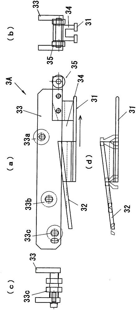
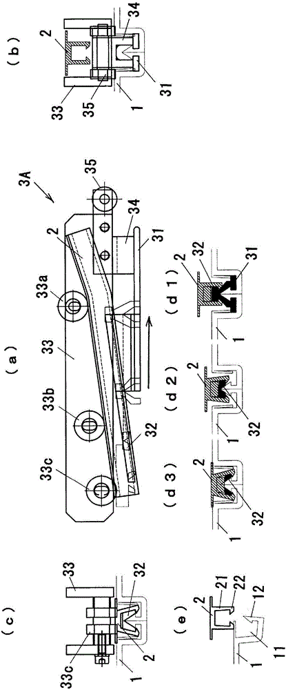
[0057] Figure 1 ~ Figure 2 The first embodiment of the slide tool for connecting face materials according to the present invention is shown. The sliding tool 3A (hereinafter, sometimes referred to as "tool") for connecting the face materials is as follows: Figure 8 As shown in (a) to (c), the surface material fitting claws 12 formed in the grooves 11 formed on the ends of the width direction of each surface material 1 and the surface material formed opposite to the protrusions 21 are used to The connecting member fitting claws 22 are respectively fitted to connect the strip-shaped inner surface members 1 (hereinafter referred to as "face materials 1") arranged side by side in the width direction to each other, and the protrusions 21 are formed in parallel across the sides of the two face materials 1. The inner surface member connection part 2 (hereinafter referred to as "surface material connection part 2") arranged at the end in the width direction is formed in parallel wit...

Embodiment 2

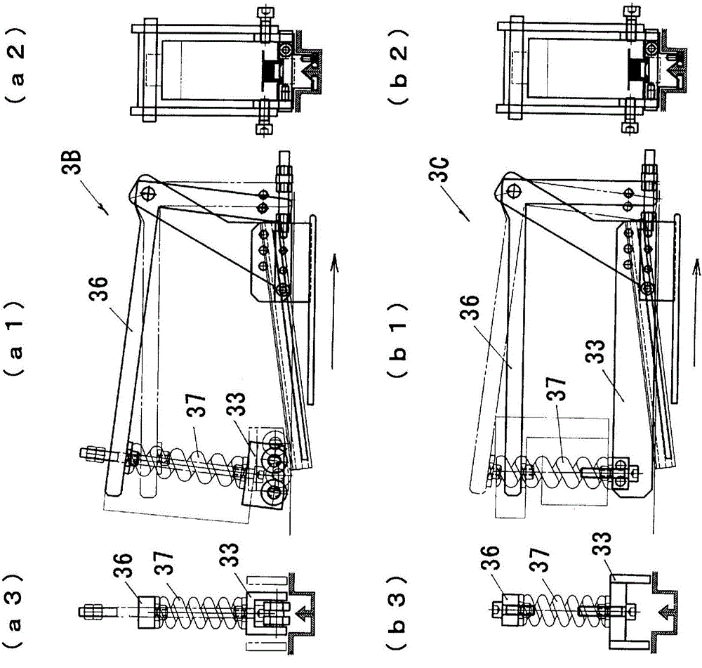
[0078] However, a traction part (not shown) is provided at the front part of the slide tool 3A in the sliding direction for connecting the surface materials, and a steel cable (not shown) is connected to the traction part, and the operator or the operator passes through the front part of the tool 3A. When a work machine such as a winch pulls the tool 3A and slides the tool 3A, for example, when a pulling part is provided in front of the pressing part 33 and the tool 3A is pulled via the pressing part 33, as in Figure 4 As shown in (b), the rear part of the pressing part 33 floats, and the surface of the surface material connecting member 2 cannot be sufficiently pressed by the pressing part 33, and the fitting claw 12 of the surface material connecting part and the fitting claw 22 of the surface material connecting part Potentially unreliable.

[0079] To prevent this floating phenomenon, such as Figure 3 ~ Figure 4 As shown in the first mode and the second mode of the seco...

Embodiment 3

[0083] Figure 5 A third embodiment of the slide tool for connecting face materials according to the present invention is shown.

[0084] Such as Figure 8 As shown in (a) to (c), the surface material connecting slide tool 3D is used to make the surface material fitting pawl 12 formed in the groove 11 formed on the end portion of the width direction of each surface material 1 and the The surface material connecting member fitting claws 22 formed opposite to the protrusions 21 are respectively fitted to connect the strip-shaped inner surface members 1 (hereinafter referred to as "surface materials 1") arranged side by side in the width direction to each other, and the protrusions 21 The inner surface member connecting member 2 (hereinafter referred to as "face material connecting member 2") arranged across the ends of the width direction of both face materials 1 is formed in parallel, and the supporting part 31 inserted into the groove 11 of the face material 1, The pressing p...


PUM


Abstract

In order to provide a slide jig for connection of surface materials, which makes it possible to easily connect the surface materials while reliably fitting fitting claws to each other, the present invention is used for connecting belt-shaped surface materials (1) provided side by side in a width direction by fitting surface material fitting claws (12) formed in grooves (11) formed in end portions in the width direction of the respective surface materials (1), and surface material connecting material fitting claws (22) formed to face protrusions (21) formed on a surface material connecting material (2) disposed to spread over end portions in the width direction of both the surface materials (1), respectively, and is provided with, integrally via a connection portion (34), a support portion (31) which is inserted into the groove (11) of the surface material (1), a protrusion guide portion (32) which is inserted between the protrusions (21) formed on the surface material connecting material (2), and a pressing portion (33) which presses the surface of the surface material connecting member (2). The support portion (31) is provided so as to be located in the front in the slide direction of a jig (3A), and the projection guide portion (32) and the pressing portion (33) are provided so as to be located in the back in the slide direction of the jig (3A).

Description

technical field [0001] The present invention relates to a sliding tool for connecting surface materials and a method for laying surface materials using the sliding tool for connecting. Background technique [0002] Conventionally, as a repair structure for existing pipes such as aged sewer pipes, a repair structure for existing pipes using a lining member to cover the entire inner surface of the existing pipes has been proposed in large numbers (for example, refer to Patent Documents 1 and 2). [0003] Among them, the plan described in Patent Document 1 is a plan for construction using blocks for repairing flow path facilities. The blocks for repairing flow path facilities are assembled to form a tubular, square, or horseshoe-shaped cylindrical body, and are integrated using plastic. An inner panel constituting an inner peripheral surface and an outer peripheral plate erected on the peripheral edge of the inner panel are formed. In addition, the solution described in Patent...

Claims


Application Information

Patent Timeline
Patent Type & Authority Applications(China)
IPC IPC(8): B29C63/30E03F3/04E03F7/00E04G21/18F16L1/00
CPCB29C63/0004B29C63/30
Inventor 森田佳伸黑川裕司桥本隆弘
Owner TAKIRON ENG
Why Eureka
Try Eureka