Backflow water storage type waterproof structure

A waterproof structure, water storage technology, applied in the direction of the engine seal, engine components, shafts, etc., can solve problems such as damage to the main shaft and bearings, and achieve the effect of improving the waterproof effect.

Pending Publication Date: 2018-07-17
尹明
View PDF1 Cites 1 Cited by
  • Summary
  • Abstract
  • Description
  • Claims
  • Application Information

AI Technical Summary

Problems solved by technology

[0004] The above-mentioned sealing structure has the following defects: although there are three sealing structures in the structure, once the liquid enters the dust cover, it cannot be discharged, and the liquid will accumulate in the dust cover after a long time of use. The three sealing structures are all connected to each other, and the liquid will eventually enter the main shaft along the gap between the three sealing structures, causing damage to the main shaft and bearings

Method used


Image

  • Backflow water storage type waterproof structure
  • Backflow water storage type waterproof structure
  • Backflow water storage type waterproof structure

Examples


Embodiment 1

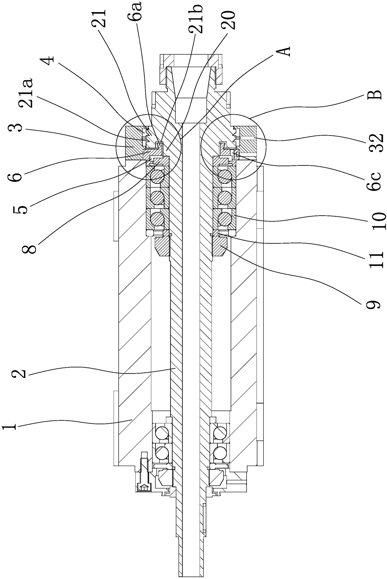
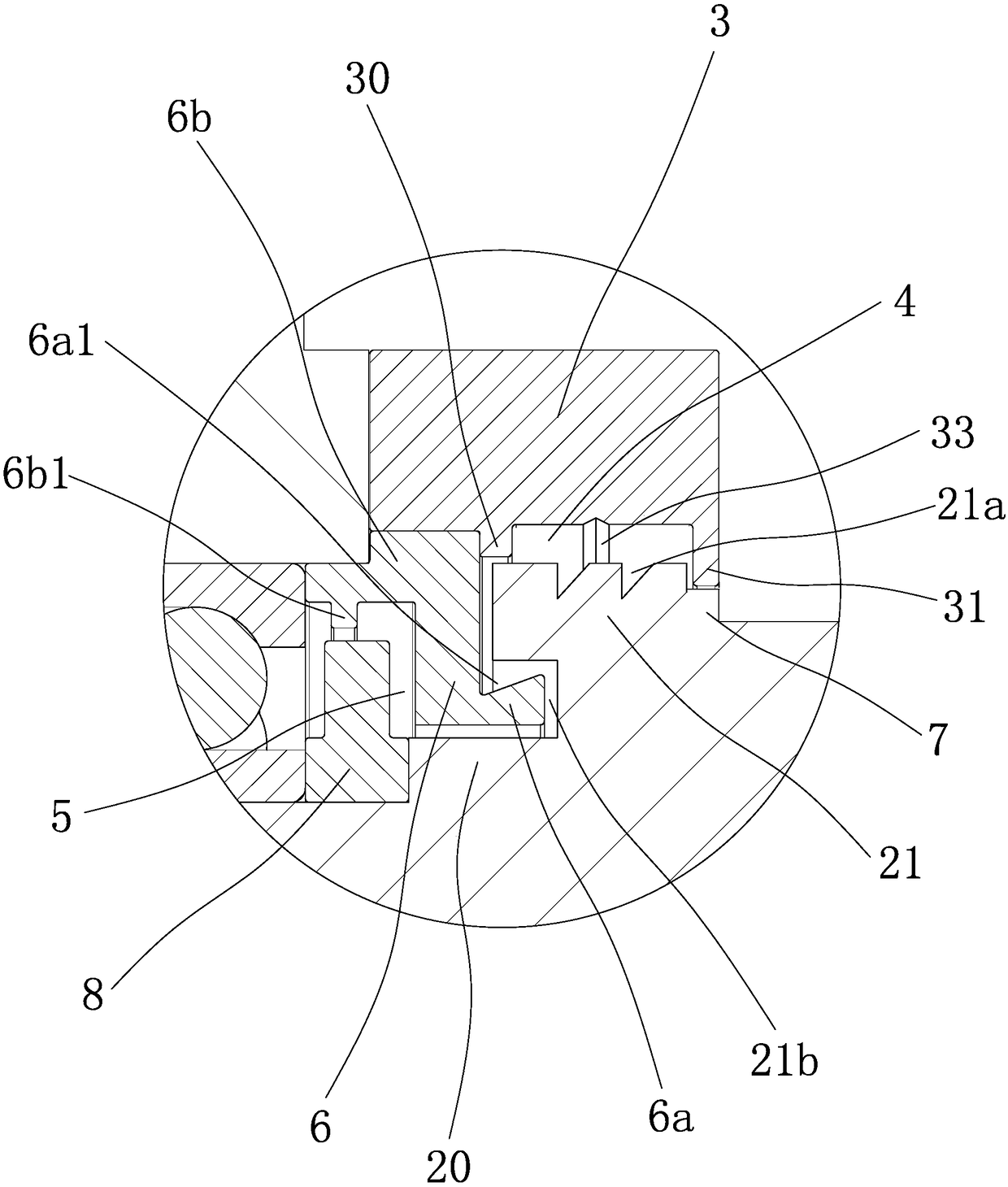
[0022] Such as figure 1 , figure 2 and image 3As shown, it includes a housing 1, a main shaft 2 arranged in the housing 1 and an end cover 3 arranged at one end of the housing 1. The outer peripheral surface of one end of the main shaft 2 has ring-shaped inner bosses 20 and outer bosses. Boss 21, the outer diameter of the outer boss 21 is greater than the outer diameter of the inner boss 20, an outer chamber 4 is formed between the outer peripheral surface of the outer boss 21 and the inner peripheral surface of the end cover 3, the An inner chamber 5 is formed between the outer peripheral surface of the inner boss 20 and the inner peripheral surface of the end cover 3, the outer chamber 4 communicates with the inner chamber 5, and the outer peripheral surface of the outer boss 21 is provided with Centrifugal groove 21a, the inner end surface of the outer boss 21 is provided with a ring-shaped relief groove 21b, the inner chamber 5 has a sealing ring 6 fixed on the end cov...

Embodiment 2

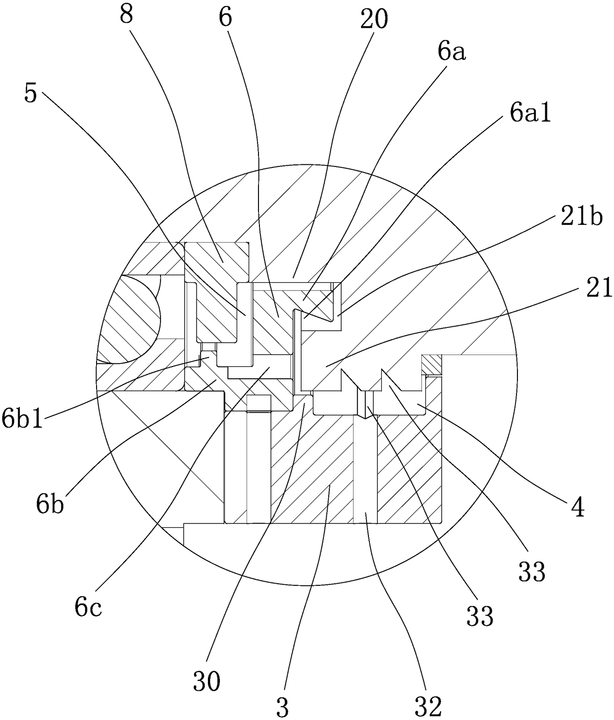
[0027] The content of this embodiment is basically the same as that of the above-mentioned embodiment 1, the difference is that this drainage structure can also be provided with two drainage passages-32 along the radial direction on the outer peripheral surface of the end cover 3, and one of the drainage passages-32 is connected Outer chamber 4 and another drain channel 1 32 communicate with inner chamber 5 , and the side of seal ring 6 opposite to sealing sleeve 8 is provided with drain channel 2 6c communicating with drain channel 1 32 communicating with inner chamber 5 .


PUM


Abstract

The invention provides a backflow water storage type waterproof structure and belongs to the technical field of machines. The backflow water storage type waterproof structure solves the problem of thepoor waterproof effect of an existing main shaft waterproof structure. The backflow water storage type waterproof structure comprises a shell, a main shaft arranged in the shell and an end cover arranged at one end of the shell. The outer peripheral surface of one end of the main shaft is provided with an inner boss and an outer boss which are both annular. A centrifugal groove is formed in the outer peripheral surface of the outer boss. An annular avoiding groove is formed in the inner end face of the outer boss. A sealing ring fixed on the end cover is arranged in an inner chamber. An annular extending portion extending into the avoiding groove is arranged on the sealing ring. A backflow groove is formed in the outer peripheral surface of the extending portion. One side face of a sealing sleeve abuts against the inner end surface of the inner boss. A drainage structure for communicating an outer chamber with the inner chamber is arranged on the end cover and the sealing ring. Four waterproof structures sequentially block liquid from entering the interior of the main shaft from outside to inside, and both the outer chamber and the inner chamber drain the liquid through the drainage structure, and the waterproof effect of the main shaft is improved.

Description

technical field [0001] The invention belongs to the technical field of machinery and relates to a waterproof structure, in particular to a backflow water storage type waterproof structure. Background technique [0002] The main shaft generally works under the working conditions of high temperature, high pressure and high speed. Under this working condition, the general moisture or dust entering the main shaft will increase the damage and wear of the main shaft and bearings or other components, thereby reducing the service life of the main shaft. However, the existing waterproof structure of the main shaft is generally realized by sealing rings and sealing rings. The sealing rings and sealing rings in this waterproof structure wear out quickly under high-speed operating conditions, and gaps will appear after the sealing rings and sealing rings are worn. Moisture and dust directly enter the main shaft through this gap, which affects the service life of the main shaft. [0003...

Claims


Application Information

Patent Timeline
Patent Type & Authority Applications(China)
IPC IPC(8): F16J15/16F16C3/02
CPCF16J15/16F16C3/02F16J15/164
Inventor 尹明尹奇
Owner 尹明
Why Eureka
Try Eureka