Welding-free stamping terminal

A welding-free, terminal technology, which is applied to the parts, connections, and contact parts of the connecting device to improve the use effect and ensure the electrical performance.

Inactive Publication Date: 2018-07-17
阜阳冈奇精密科技有限公司
View PDF4 Cites 0 Cited by
  • Summary
  • Abstract
  • Description
  • Claims
  • Application Information

AI Technical Summary

Problems solved by technology

[0004] Aiming at the deficiencies of the prior art, the present invention provides a solder-free stamping terminal. By inventing the stamping terminal leg, the stamping terminal is punched out and closel

Method used


Image

  • Welding-free stamping terminal

Examples


Embodiment Construction

[0015] The following will clearly and completely describe the technical solutions in the embodiments of the present invention with reference to the accompanying drawings in the embodiments of the present invention. Obviously, the described embodiments are only some, not all, embodiments of the present invention. Based on the embodiments of the present invention, all other embodiments obtained by persons of ordinary skill in the art without making creative efforts belong to the protection scope of the present invention.

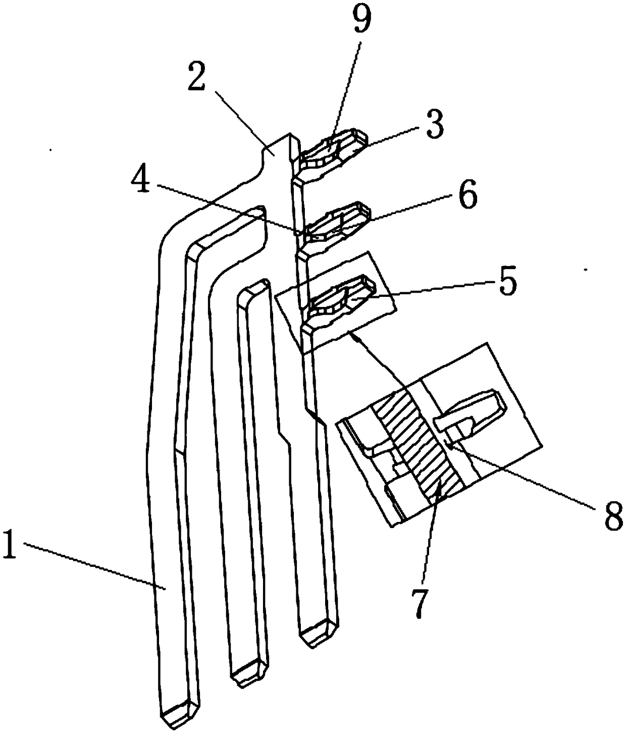
[0016] see figure 1 , a solder-free stamping terminal, including a terminal 1 and a PCB 7, a bracket 2 is fixedly installed on the terminal 1, a foot 3 is fixedly installed on the bracket 2, and there is a positioning point on both sides of the foot 3, and the terminal 1 is inserted according to the positioning point After the PCB hole 8 is inside, the terminal 1 is clamped on the upper and lower sides of the PCB7, and the terminal 1 is fastened on the PCB7. T...


PUM


Abstract

The invention relates to the technical field of stamping terminal supporting foot forming, and discloses a welding-free stamping terminal. The stamping terminal comprises a terminal and a PCB. A bracket is fixedly mounted on the terminal, the bracket is fixedly mounted with a supporting foot, and the surface of the supporting is designed with a supporting R angle. Both sides of which are welded with the positioning of the supporting in the die, and the other two sides of the R angle of the supporting foot are provided with the upper and lower grooves of the supporting foot edge. By setting theupper and lower grooves of the supporting foot edge of the welding-free stamping terminal, the contact surface on the upper and lower grooves of the supporting foot edge is directly contacted and fixed with the PCB hole. The terminal is shrink in the process of inserting into the PCB hole and make the insert smooth, the terminal is expanded when inserted into the PCB hole and located, so that thecorner surface of the terminal R is more closely attached to the PCB hole and ensure the electrical performance. The circuit between the PCB and the terminal is ensured after the terminal is inserted, and the manual soldering and wave soldering are eliminated, which greatly improves the use effect of the welding-free stamped terminal.

Description

technical field [0001] The invention relates to the technical field of stamping terminal leg forming, in particular to a welding-free stamping terminal. Background technique [0002] Solder-free stamping terminal is an accessory product suitable for electrical connection. It is industrially classified into the category of connectors and can be widely used in PCB assembly in industrial, consumer electronics and other electronic industries. In the current technology industry, soldering of stamped terminals (DIP plug-in components) is tin soldering, which is manifested in manual soldering, wave soldering and other methods. The disadvantages of the existing technology are high production cost and unstable product quality. The common quality problems are manifested in common welding problems such as empty soldering, virtual soldering, false soldering, and tin beads. In particular, the problem of false soldering cannot be found during the production inspection process. Often the ...

Claims


Application Information

Patent Timeline
IPC IPC(8): H01R13/02H01R13/639H01R12/71
CPCH01R13/02H01R12/712H01R13/639
Inventor 周玉振
Owner 阜阳冈奇精密科技有限公司
Why Eureka
Try Eureka