Supercharge Your Innovation With Domain-Expert AI Agents!

Gaseous fuel injectors

一种气体燃料、喷射器的技术,应用在燃料喷射装置、电气元件、装料系统等方向,能够解决双燃料发动机代价高、复杂等问题

Active Publication Date: 2018-07-17
DELPHI TECH IP LTD
View PDF9 Cites 1 Cited by
  • Summary
  • Abstract
  • Description
  • Claims
  • Application Information

AI Technical Summary

Problems solved by technology

However, this device is more expensive and more complex than the dual-fuel engines mentioned above

Method used


Image

  • Gaseous fuel injectors
  • Gaseous fuel injectors
  • Gaseous fuel injectors

Examples


Embodiment Construction

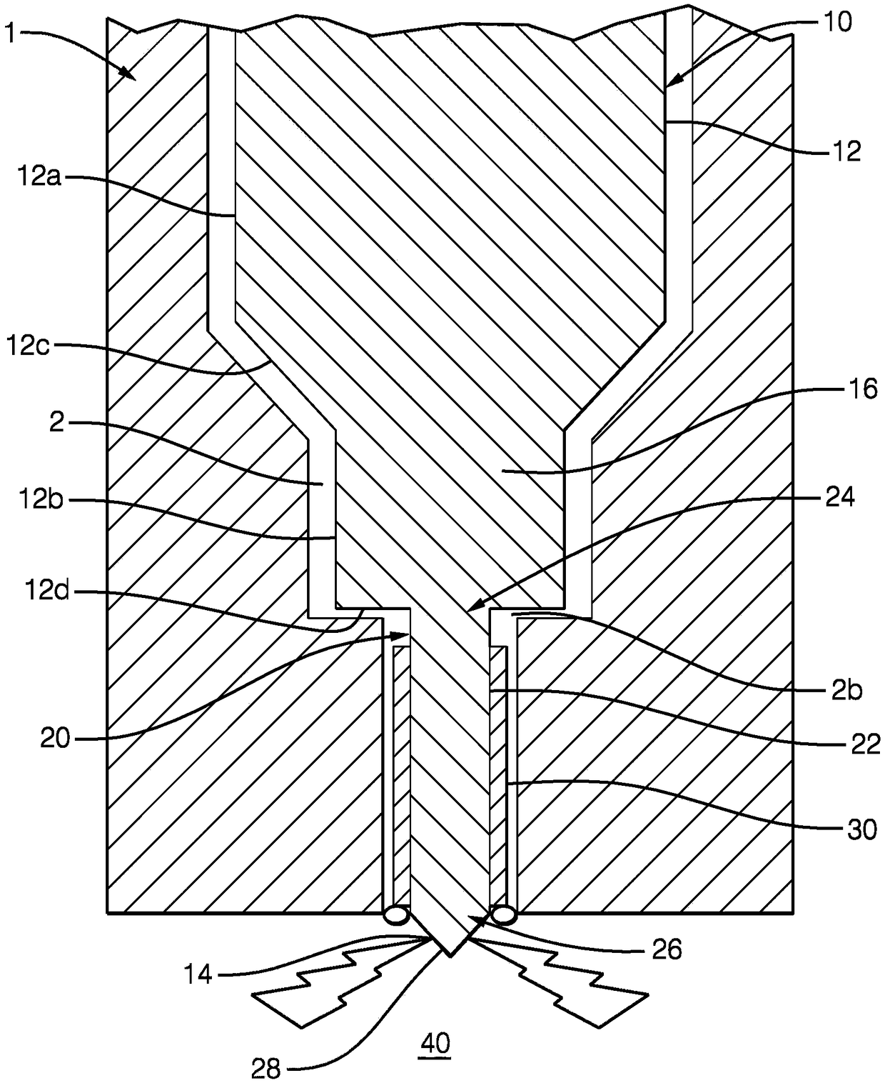
[0034] As shown in the figures, the present invention includes a gaseous fuel injector 10 for supplying gaseous fuel to a gaseous fuel combustion engine (not shown). The gaseous fuel injector 10 includes an injector housing 12 adapted to receive an injector assembly (not specifically shown) and supply gaseous fuel thereto, the injector housing 12 having: an inlet (not shown) at a first end; A nozzle 20, 20' with an outlet 14 at the second open end; and a chamber 16 between the inlet and the outlet 14, characterized in that the injector housing 12 includes an ignition device at the second open end.

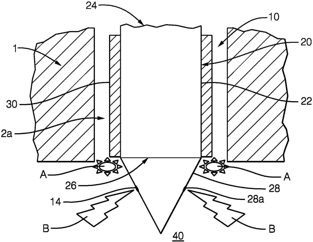
[0035] figure 1 and figure 2 A first embodiment of the present invention is shown in .

[0036] If you can figure 2 As seen more clearly in , nozzle 20 includes, as part of housing 12 , a main nozzle body 22 that is generally an elongated hollow cylindrical portion. The nozzle 20 includes a first open end 24 in communication with the chamber 16 of the gaseous fuel injector 10...


PUM


Abstract

The invention comprises a gaseous fuel injector (10) for supplying gaseous fuel to a gaseous fuel combustion engine. The gaseous fuel injector (10) comprises an injector housing (12) adapted to receive an injector assembly (28) and supply gaseous fuel thereto. The injector housing (12) has an inlet at a first end, a nozzle (20, 20') with an outlet (14) at a second open end (26, 26') and a chamber(16) between the inlet and the outlet (14). The injector housing (12) comprises an ignition arrangement at the second open end (26, 26'). The invention also extends to a gaseous fuel combustion enginecomprising a gaseous fuel injector (10) and an ignition arrangement according to the invention.

Description

technical field [0001] The present invention generally relates to the field of gaseous fuel injectors. In particular, but not exclusively, the present invention relates to improved ignition arrangements for gaseous fuel injectors in gaseous fuel combustion engines. Background technique [0002] Gas fuel combustion engines use gaseous fuels such as compressed natural gas (GNG) or liquefied natural gas (LNG). These engines require gaseous fuel injectors to supply a calculated amount of gas to the combustion chamber of the engine for ignition. [0003] A gaseous fuel injector includes a nozzle with a valve at an outlet end. In what is known as spark ignition port injection (SI-PI) gas fueled engines, gas is supplied into the inlet manifold and from there, valves control the flow of gas into the combustion chamber for ignition by means of an ignition source. This mechanism is usually obtained by modifying an existing gasoline engine which has proven to be inefficient. The ig...

Claims


Application Information

Patent Timeline
Patent Type & Authority Applications(China)
IPC IPC(8): F02M21/02F02M57/06F02P15/00F02M53/04
CPCF02M21/0275F02M21/0296F02P13/00F02P15/006H01T13/40H01T13/00Y02T10/30
Inventor L·潘瑟尔M·兰伯特
Owner DELPHI TECH IP LTD
Features
  • R&D
  • Intellectual Property
  • Life Sciences
  • Materials
  • Tech Scout
  • Unparalleled Data Quality
  • Higher Quality Content
  • 60% Fewer Hallucinations
Learn More