Magnetic transmission

A speed changer and magnet technology, applied in the field of radial spaced magnetic speed changers, can solve the problems of not being able to change the speed ratio continuously, changing the speed ratio discontinuously, etc.

Active Publication Date: 2018-07-17
HITACHI METALS LTD
View PDF6 Cites 5 Cited by
  • Summary
  • Abstract
  • Description
  • Claims
  • Application Information

AI Technical Summary

Problems solved by technology

[0008] However, although the magnetic multi-stage transmission mechanism of Patent Document 1 can change the speed ratio discontinuously, there is a problem that the speed ratio cannot be changed continuously.

Method used


Image

  • Magnetic transmission
  • Magnetic transmission
  • Magnetic transmission

Examples


Embodiment approach 1

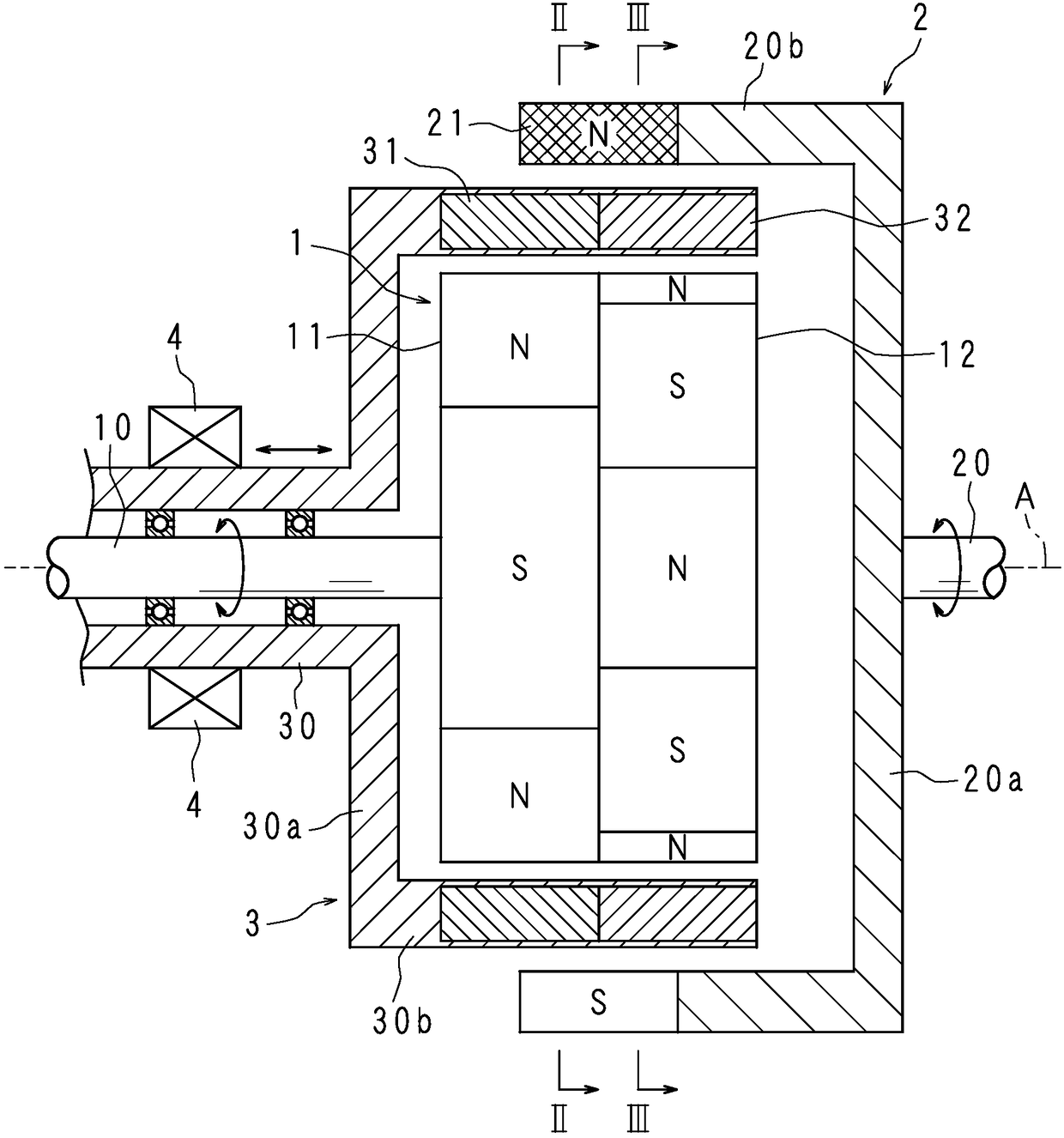
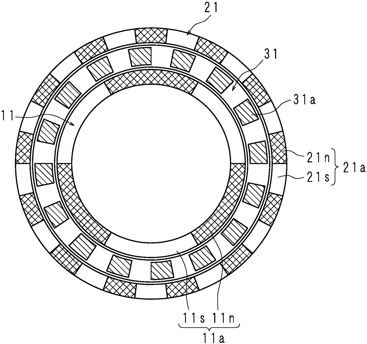
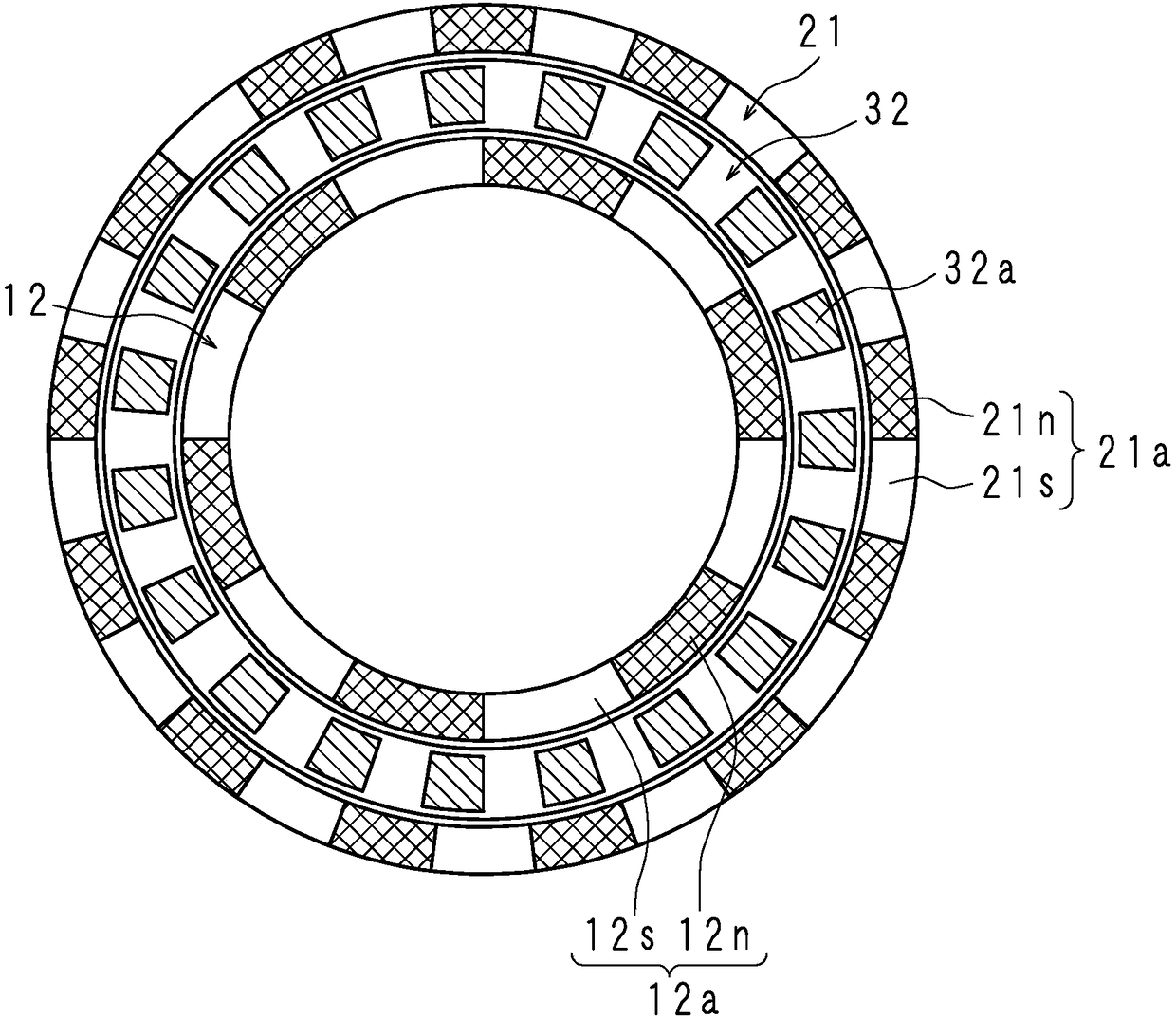
[0033] figure 1 It is a side sectional view showing the structure of the magnetic transmission of Embodiment 1, figure 2 It is the II-II line sectional view of the magnetic speed changer, image 3 It is the III-III line sectional view of the magnetic transmission. The magnetic variator according to Embodiment 1 of the present invention is a radially spaced magnetic gear device for outputting input torque at a variable speed. The magnetic speed change machine includes: a disc-shaped inner rotor (inner magnet row) 1 coaxially arranged, an outer rotor (outer magnet row) 2, and a magnetic field modulation stator (magnetic field adjusting stator) arranged between the inner rotor 1 and the outer rotor 2. body row) 3. The magnetic transmission further includes an input shaft (input member) 10 for inputting torque to the magnetic transmission and an output shaft (output member) 20 for outputting the shifted torque. The input shaft 10 and the output shaft 20 are formed of non-magn...

Embodiment approach 2

[0069] Figure 5 It is a side sectional view showing the structure of the magnetic transmission of Embodiment 2. The magnetic transmission of Embodiment 2 includes the same inner rotor 1, outer rotor 2, and field modulating stator 3 as Embodiment 1, and further includes an input rotation speed detection unit 51 for detecting the rotation speed of the input shaft 10, and a unit for detecting the rotation speed of the output shaft 20. The output rotation speed detection part 52 and the control part 6 which controls the operation|movement of the actuator 4 based on the detected rotation speed are output.

[0070] The input rotational speed detection part 51 includes, for example: a magnetic pickup that sends a signal proportional to the rotational speed of the input shaft 10, a non-contact sensor including a Hall element, and a counting circuit that measures the number of pulses from the non-contact sensor. The detection unit 51 calculates the rotational speed of the input shaft...


PUM


Abstract

A magnetic transmission is provided with an inner rotor (1), an outer rotor (2), and a magnetic field-modulating stator (3) disposed coaxially between the inner rotor (1) and the outer rotor (2). Theinner rotor (1) is provided with a first magnet row (11) and a second magnet row (12) that are disposed in parallel in the direction of the central axis (A) and disposed at different pitches along thecircumferential direction. The outer rotor (2) is provided with a magnet row that is disposed along the circumferential direction. The magnetic field-modulating stator (3) is provided with a first magnetic body row (31) and a second magnetic body row (32) that oppose the first magnet row (11) and the second magnet row (12), respectively. Moreover, by moving the inner rotor (1) and the magnetic field-modulating stator (3) in the direction of the central axis (A) while maintaining the opposing relationship between the first magnetic body row (31) and the second magnetic body row (32) and the first magnet row (11) and the second magnet row (12), the position of opposition between the outer rotor (2) and the first magnet row (11) and second magnet row (12) is varied continuously.

Description

technical field [0001] The invention relates to a radial interval magnetic speed changer capable of continuously changing the speed ratio. Background technique [0002] Patent Document 1 discloses a radially spaced magnetic multi-stage transmission mechanism capable of discontinuously switching gear ratios. The magnetic multi-stage transmission mechanism includes a plurality of disk-shaped inner rotors arranged apart from each other in the direction of the rotation axis, a plurality of annular outer rotors arranged on the outer peripheral side of each inner rotor, and a plurality of ring-shaped outer rotors arranged between the inner rotor and the outer rotor. Between the ring-shaped stator. The inner rotor is arranged on the input shaft, and the plurality of inner rotors are respectively arranged with different numbers of magnetic pole pairs in the circumferential direction. The outer rotor is arranged on the output shaft, and the plurality of outer rotors are respectivel...

Claims


Application Information

Patent Timeline
IPC IPC(8): F16H49/00
CPCF16H49/00H02K21/024H02K49/102H02K49/106H02K2213/09H02K11/215
Inventor 木本昭洋
Owner HITACHI METALS LTD
Why Eureka
Try Eureka