A can compression device

A technology for compression devices and cans, which is applied to presses, manufacturing tools, etc., can solve problems such as inconvenient operation, time-consuming and laborious, and low efficiency, and achieve the effects of improving safety, improving compression efficiency, and simple operation

Active Publication Date: 2019-07-02
许冰
View PDF7 Cites 0 Cited by
  • Summary
  • Abstract
  • Description
  • Claims
  • Application Information

AI Technical Summary

Problems solved by technology

Since the processing method of cans is manual crushing, the efficiency of manual crushing is relatively low, which is time-consuming and laborious, which brings inconvenience to the operation

Method used


Image

  • A can compression device
  • A can compression device
  • A can compression device

Examples


Embodiment Construction

[0014] The following is further described in detail through specific implementation methods:

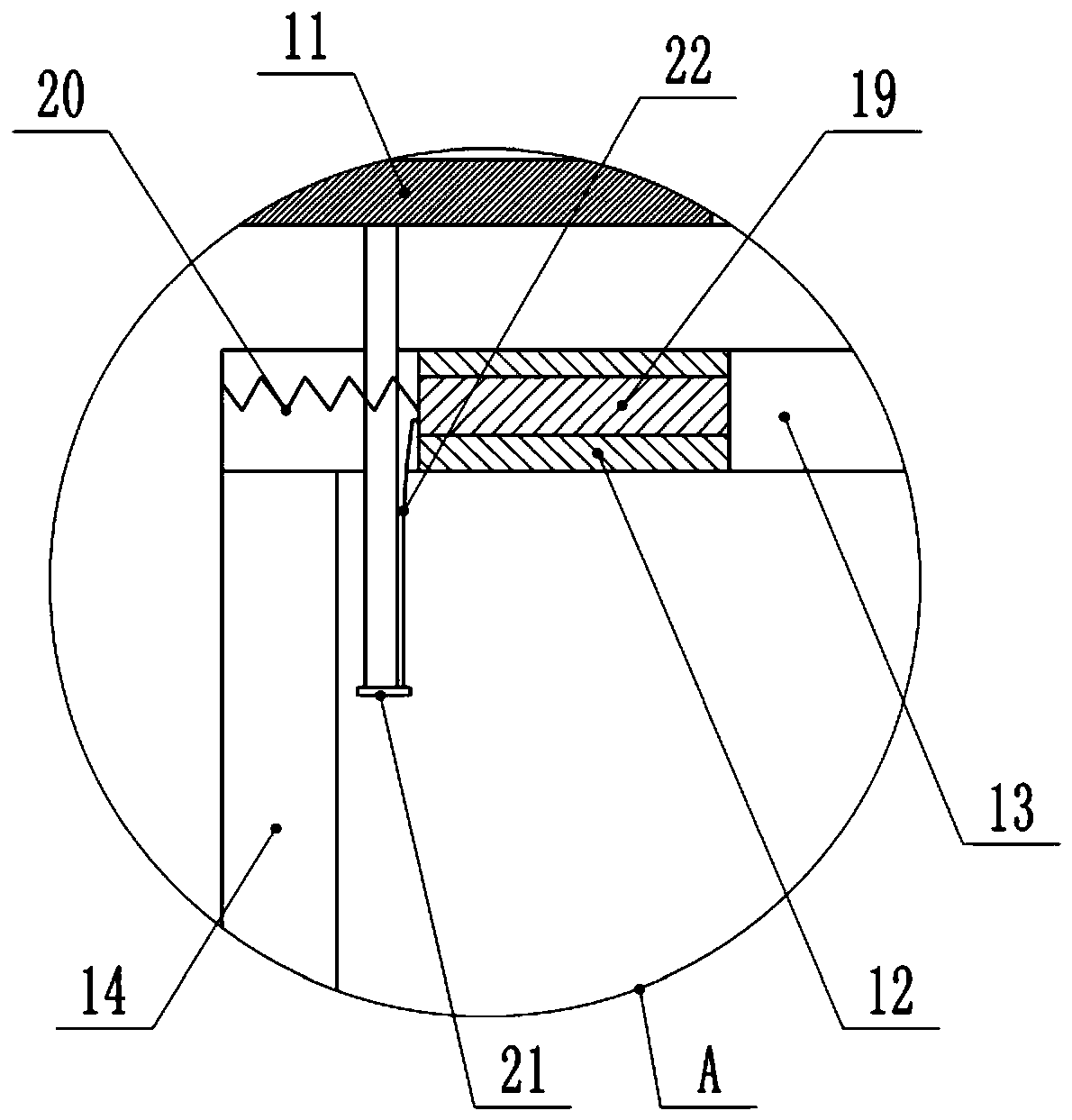
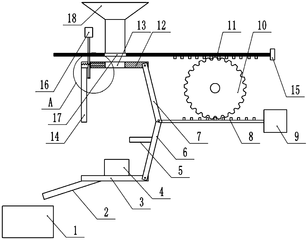
[0015] The reference signs in the drawings of the description include: collection box 1, material guide plate 2, bottom plate 3, upper top block 4, push rod 5, first connecting plate 6, second connecting plate 7, second meshing teeth 8, the first A cylinder 9, a gear 10, a horizontal plate 11, a top plate 12, a second feed port 13, a baffle plate 14, a timing switch 15, a second cylinder 16, a first feed port 17, a feed hopper 18, a switch plate 19, Spring 20, cover plate 21, steel wire rope 22.

[0016] The embodiment is basically as attached Figure 1-Figure 2 Shown: a can compression device, including a frame, the frame is provided with a compression mechanism, the compression mechanism includes a bottom plate 3 welded on the frame, the top of the bottom plate 3 is welded with an upper top block 4, the left side of the bottom plate 3 A material guide plate 2 is welded, and a col...


PUM


Abstract

The invention relates to a ring-pull can compression device which comprises a rack. A compression mechanism is arranged on the rack. A first air cylinder is arranged on the outer side of the compression mechanism. The compression mechanism comprises a bottom plate and a top plate in sliding connection to the rack. The side portion of the bottom plate is rotationally connected with a first connecting plate. The side portion of the top plate is rotationally connected with a second connecting plate. The second connecting plate is rotationally connected with the first connecting plate. The side portion of the first connecting plate is rotationally connected with a piston rod of the first air cylinder. The side portion of the top plate is connected with a baffle. A second air cylinder and a feeding hopper are arranged above the top plate. A transverse plate slides at the bottom of the feeding hopper and is provided with a first feeding opening. A timing switch is arranged above the first air cylinder. A gear is arranged between the transverse plate and the piston rod of the first air cylinder. A second feeding opening is formed in the top plate. A switch plate is in sliding connection to the top plate. A spring is connected between the switch plate and the top plate. A through hole is formed in the top plate, the top plate is covered with a cover plate, and a pull rope is connectedbetween the cover plate and the switch plate. According to the scheme, ring-pull can automatic compression is achieved.

Description

technical field [0001] The invention relates to the field of daily necessities processing, in particular to a compression device for pop cans. Background technique [0002] Daily necessities, also known as daily necessities, are items and daily necessities used by ordinary people, that is, household items, household food, household utensils and household appliances. After the daily necessities are used, the empty shells of daily necessities will become waste products. Since most of the empty shells of daily necessities are hollow containers, which are light in weight and large in volume, in order to reduce the occupation of space, it is often necessary to compress the empty shells. Dropping, such as the treatment of cans, is to crush them manually. Because the processing method of pop cans is manually crushed, the efficiency of manual crushing is relatively low, and it is time-consuming and laborious, which brings inconvenience to the operation. Contents of the invention ...

Claims


Application Information

Patent Timeline
Patent Type & Authority Patents(China)
IPC IPC(8): B30B9/32B30B15/30B30B15/32
CPCB30B9/321B30B15/30B30B15/32
Inventor 刘泽辉
Owner 许冰
Why Eureka
Try Eureka