Automatic scum collecting system

An automatic collection and scum technology, which is applied in waterway system, grease/oily substance/floating matter removal device, water/sludge/sewage treatment, etc., can solve the problems of waste of manpower and material resources, being washed away, and high operating cost. Achieve the effect of reducing construction cost and operating cost, and simple structure

Inactive Publication Date: 2018-07-20
WUHAN SHENGYU DRAINING SYST
View PDF0 Cites 4 Cited by
  • Summary
  • Abstract
  • Description
  • Claims
  • Application Information

AI Technical Summary

Problems solved by technology

This method of slag removal has the following problems: 1. The slag filter is easily damaged or washed away due to water washing; 2. Whether the slag filter is full needs to be checked regularly. If the slag filter is full, it is not cleaned in time , it is easy to block the water inlet pipe, which will affect flood discharge in rainy weat

Method used


Image

  • Automatic scum collecting system
  • Automatic scum collecting system

Examples


Embodiment 1

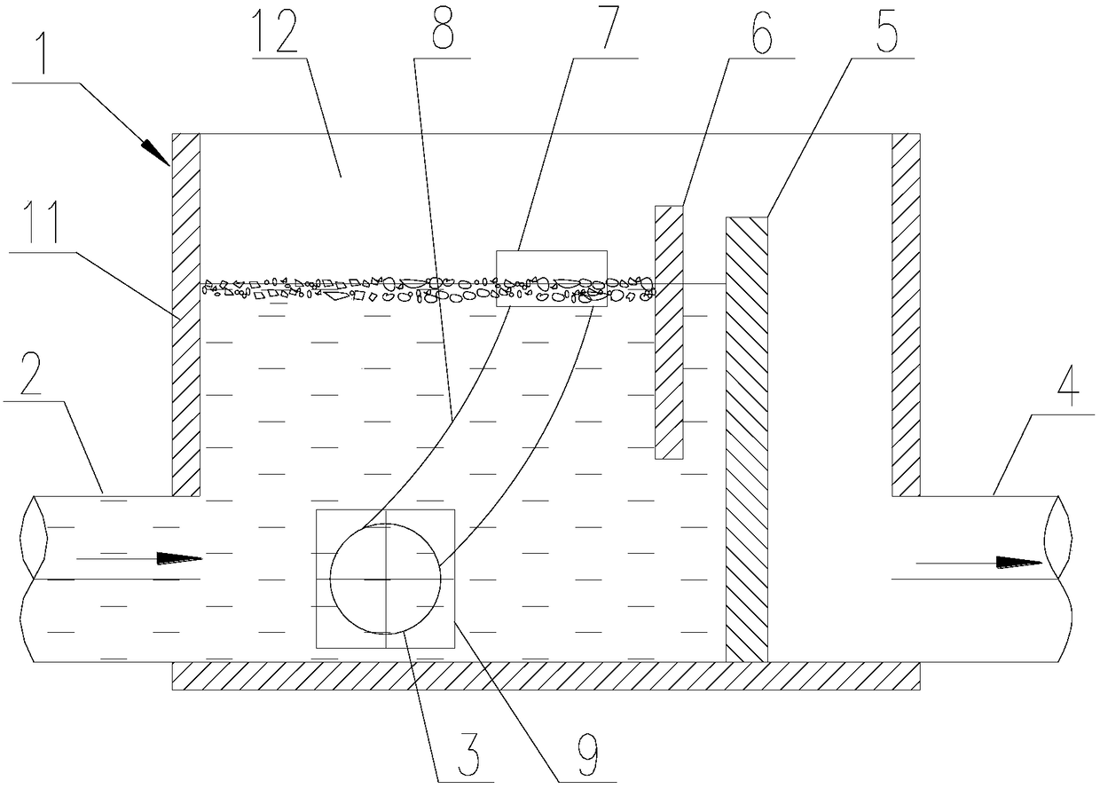
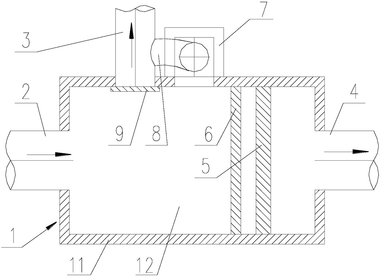
[0030] see figure 1 with figure 2 As shown, on the basis of the above-mentioned technical solution, the first hydraulic switch is a retractable weir gate 5 of the discharge outlet. The height that the weir door 5 of the drain outlet protrudes is higher than the highest drainage position of the drain outlet.

[0031] In practical applications, the first hydraulic switch can also be a gate or a gate valve, and the gate or gate valve is arranged at the drain.

Embodiment 2

[0033] The diversion well wall 11 is also provided with a sewage outlet, the sewage outlet communicates with the inner cavity 12 of the diversion well, and the sewage outlet communicates with the inner cavity 12 of the diversion well and the sewage treatment plant through the sewage interceptor 3, and the minimum water inlet position of the scum collection inlet is at a level of The water outlet of the scum collecting pipe 8 is connected to the sewage intercepting pipe 3 at a level higher than the highest water inlet position of the sewage outlet. The system of the present invention also includes a second hydraulic switch for controlling the water output of the sewage outlet. The second hydraulic switch is located in front of the connection between the water outlet pipe mouth and the sewage intercepting pipe 3 . Specifically, the second hydraulic switch is the sewage outlet gate 9, and the sewage outlet gate 9 is arranged at the sewage outlet.

[0034] In practical applicatio...

Embodiment 3

[0036] The baffle plate 6 is a fixed baffle plate, the two sides of the fixed baffle plate are fixedly connected with the shunt well wall 11, the horizontal height of the upper edge of the fixed baffle plate is higher than the horizontal height of the highest water inlet position of the scum collection inlet, and the lower edge of the fixed baffle plate is The water level in the diversion well 1 controlled by the hydraulic switch is always higher than the level of the lower edge of the fixed baffle.


PUM


Abstract

The invention discloses an automatic scum collecting system, and relates to the technical field of sewage treatment. The system is used for collecting scum in a diversion well, the diversion well comprises a diversion well wall and a diversion well inner cavity surrounded by the diversion well wall, and a water inlet and a water outlet which are communicated with the inner cavity of the diversionwell are formed in the diversion well wall. The system comprises a scum collecting inlet and a scum collecting tube; the scum collecting inlet is formed in the scum well wall, and the scum collectinginlet is communicated with the inner cavity of the scum well; the horizontal height of the lowest water inlet position of the scum collecting inlet is larger than the horizontal height of the highestwater inlet position of the water inlet; the scum collecting tube comprises a water inlet pipe opening and a water outlet pipe opening, the horizontal height of the water outlet pipe opening is smaller than the horizontal height of the water inlet pipe opening, and the water inlet pipe opening is communicated with the scum collection inlet. The system has the advantages that scum in sewage can becollected automatically, the structure is simple, and the manufacturing cost and the operation cost are greatly reduced.

Description

technical field [0001] The invention relates to the technical field of sewage treatment, in particular to an automatic scum collection system. Background technique [0002] In the prior art, diversion wells are used for sewage treatment. On sunny days, the domestic sewage is intercepted through diversion wells and enters the sewage treatment plant. After being treated by the sewage treatment plant, it enters the natural water body. In the middle and late stages, the rainwater is relatively clean, and can be directly discharged into natural water bodies after being diverted through diversion wells. Domestic sewage and initial rainwater contain a large amount of scum, which includes suspended solids and floating pollutants, and gathers in the diversion well. Generally, a slag filter is installed in the diversion well, and the scum in the diversion well is collected through the scum filter. When the scum filter is full, the scum filter is lifted out of the diversion well manu...

Claims


Application Information

Patent Timeline
IPC IPC(8): E03F5/10E03F5/14
CPCE03F5/10E03F5/101E03F5/107E03F5/14
Inventor 李习洪段洪斌
Owner WUHAN SHENGYU DRAINING SYST
Why Eureka
Try Eureka