
a new fan

A fresh air blower and blower technology, applied in mechanical equipment, space heating and ventilation, space heating and ventilation details, etc., can solve problems such as uneven distribution of fresh air, and achieve long service life and compact overall structure

Active Publication Date: 2020-06-02
广东艾瑞克林科技有限公司
View PDF7 Cites 1 Cited by
  • Summary
  • Abstract
  • Description
  • Claims
  • Application Information

AI Technical Summary

Problems solved by technology

[0004] In view of the deficiencies of the prior art above, the purpose of the present invention is to provide a new fan, which aims to solve the technical problem of uneven distribution of fresh air on the filter element in the existing new fan

Method used


Image

  • a new fan
  • a new fan
  • a new fan

Examples


Embodiment Construction

[0024] The present invention provides a fresh fan. In order to make the purpose, technical solution and effect of the present invention more clear and definite, the present invention will be further described in detail below with reference to the accompanying drawings and examples. It should be understood that the specific embodiments described here are only used to explain the present invention, not to limit the present invention.

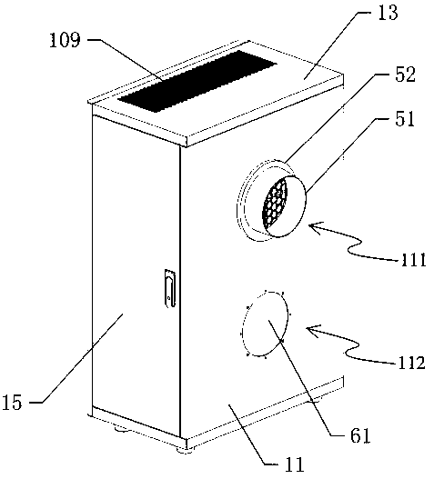
[0025] see Figure 2 to Figure 7 , The present invention provides a new fan. Words related to orientation such as "vertical" and "height" described herein are intended to facilitate explanation in conjunction with the accompanying drawings, and are not intended to limit the present invention. For example, attach figure 2 Even if the fresh air blower is placed horizontally, words such as "vertical" and "height" become words such as "horizontal", "length" or "width" accordingly, and the fresh air blower can still work normally without affecting t...


PUM


Abstract

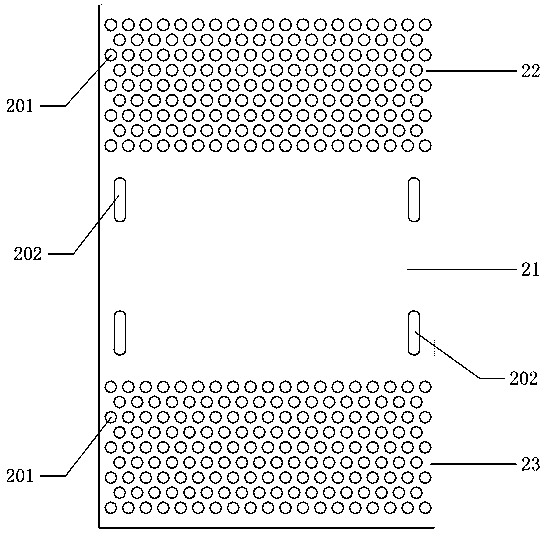
The invention discloses a fresh air ventilator. The fresh air ventilator comprises a shell, a filter element and a draught fan, wherein the filter element and the draught fan are arranged in the shell; a first air inlet is formed in the upper portion of a front door panel of the shell; an air uniformizing plate is detachably arranged on the inner side of the front door panel of the shell; the middle portion of the air uniformizing plate is provided with a windproof area; the upper portion and the lower portion of the air uniformizing plate are provided with an upper ventilating area provided with a plurality of vent holes and a lower ventilation area provided with a plurality of vent holes; the filter element is located between the inlet side of the draught fan and the air uniformizing plate. The fresh air ventilator provided by the invention achieves the air distribution and air uniformizing effects and can guarantee that fresh air passes through the filter element uniformly, and it is guaranteed that the overall structure of the fresh air ventilator is compact; accordingly, the whole filter element is fully utilized, and the service life of the filter element is longer.

Description

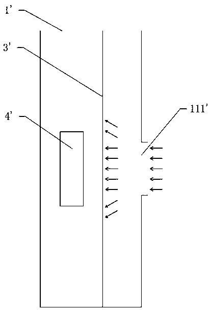
technical field [0001] The invention relates to the technical field of air treatment equipment, in particular to a fresh fan. Background technique [0002] The fresh air is used to draw outdoor fresh air, and after filtering the fresh air to form clean air, it is sent into the room. figure 1 Shown is the conventional layout of the air inlet, filter element and blower fan of the new fan in the prior art, that is, the air inlet 111' is arranged in the center of the front door panel 11', and the fan 4' is arranged in the center of the housing 1'. When the outdoor fresh air is sucked into the housing of the fresh fan, it mainly passes through the middle of the filter element 3' and finally passes through the air outlet ( figure 1 not shown in ) discharge into the chamber. This setting has the following disadvantages: (1) Fresh air mainly passes through the middle of the filter element, so the accumulation rate of dirt in the middle of the filter element is relatively high, the...

Claims


Application Information

Patent Timeline
Patent Type & Authority Patents(China)
IPC IPC(8): F24F1/0073F24F1/0093F24F13/28F24F13/08
CPCF24F1/0007F24F13/08F24F13/28F24F2221/34F24F8/10F24F8/108
Inventor 张扬梁远盛
Owner 广东艾瑞克林科技有限公司
Learn More