Sounding anti-radiation device and rocketsonde
A technology of anti-radiation device and transmitting antenna, applied in the direction of instruments, etc., can solve problems such as residual correction error, and achieve the effect of high measurement accuracy
- Summary
- Abstract
- Description
- Claims
- Application Information
AI Technical Summary
Problems solved by technology
Method used
Image
Examples
Embodiment 1
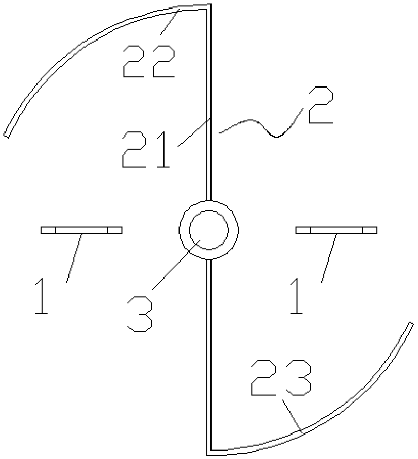
[0031] figure 1 A schematic structural view of the sounding radiation protection device provided in Embodiment 1 of the present invention; figure 1 As shown, the sounding radiation protection device provided by Embodiment 1 of the present invention includes a thermistor 1 and a sun visor 2;
[0032] Two thermistors 1 are arranged oppositely, and the two thermistors 1 are separated by the sun visor 2;
[0033] The sun visor 2 includes a partition 21, a first baffle 22 and a second baffle 23, the two thermistors 1 are separated by the partition 21, the first baffle 22 and the second baffle 23 The second baffles 23 are respectively disposed on both sides of the partition 21 and connected to the partition 21 .
[0034] Specifically, a transmitting antenna 3 is also included, and the transmitting antenna 3 is installed on the partition plate 21 .
[0035] The use of two thermistors 1 can well ensure the state consistency between the two thermistors 1, and the two opposite thermi...
Embodiment 2
[0037] The sounding radiation protection device provided in the second embodiment is a further improvement on the sounding radiation protection device provided in the first embodiment, in the first embodiment and figure 1 On the basis of the above, the sounding radiation protection device provided in the second embodiment includes a thermistor 1 and a sun visor 2;
[0038] Two thermistors 1 are arranged oppositely, and the two thermistors 1 are separated by the sun visor 2;
[0039] The sun visor 2 includes a partition 21, a first baffle 22 and a second baffle 23, the two thermistors 1 are separated by the partition 21, the first baffle 22 and the second baffle 23 The second baffles 23 are respectively disposed on both sides of the partition 21 and connected to the partition 21 .
[0040] Specifically, a transmitting antenna 3 is also included, and the transmitting antenna 3 is installed on the partition plate 21 .
[0041] The use of two thermistors 1 can well ensure the st...
Embodiment 3
[0044] The sounding radiation protection device provided in the third embodiment is a further improvement on the sounding radiation protection device provided in the first embodiment, in the first embodiment and figure 1 On the basis of the above, the sounding radiation protection device provided in the third embodiment includes a thermistor 1 and a sun visor 2;
[0045] Two thermistors 1 are arranged oppositely, and the two thermistors 1 are separated by the sun visor 2;
[0046] The sun visor 2 includes a partition 21, a first baffle 22 and a second baffle 23, the two thermistors 1 are separated by the partition 21, the first baffle 22 and the second baffle 23 The second baffles 23 are respectively disposed on both sides of the partition 21 and connected to the partition 21 .
[0047] Specifically, a transmitting antenna 3 is also included, and the transmitting antenna 3 is installed on the partition plate 21 .
[0048] The use of two thermistors 1 can well ensure the stat...
PUM
 Abstract
Description
Claims
Application Information
 - R&D
- Intellectual Property
- Life Sciences
- Materials
- Tech Scout
- Unparalleled Data Quality
- Higher Quality Content
- 60% Fewer Hallucinations
Browse by: Latest US Patents, China's latest patents, Technical Efficacy Thesaurus, Application Domain, Technology Topic, Popular Technical Reports.
© 2025 PatSnap. All rights reserved.Legal|Privacy policy|Modern Slavery Act Transparency Statement|Sitemap|About US| Contact US: help@patsnap.com

