
Design method for access of flexible multi-state switch to distribution network

A design method, multi-state technology, applied to AC networks with the same frequency from different sources, etc., can solve the problems of not taking into account the dual fluctuations of distributed power and load in the distribution network in detail, and difficult to adapt to technical economy, etc. The effect of achieving good computing performance

Active Publication Date: 2018-07-20
INST OF ELECTRICAL ENG CHINESE ACAD OF SCI +2
View PDF4 Cites 13 Cited by
  • Summary
  • Abstract
  • Description
  • Claims
  • Application Information

AI Technical Summary

Problems solved by technology

[0006] The purpose of the present invention is to overcome the shortcomings of the prior art, and solve the problem that the design of the existing flexible multi-state switch connected to the distribution network does not consider in detail the dual volatility of the distributed power supply and the load in the distribution network, and the flexible multi-state switch and the distribution network Optimizing the matching relationship of the middle tie switch leads to the problem that the design result is difficult to adapt to the future technical economy. An optimal design method for the flexible multi-state switch connected to the distribution network is proposed.

Method used


Image

  • Design method for access of flexible multi-state switch to distribution network
  • Design method for access of flexible multi-state switch to distribution network
  • Design method for access of flexible multi-state switch to distribution network

Examples


Embodiment Construction

[0021] The present invention will be further described below in conjunction with the accompanying drawings and specific embodiments.

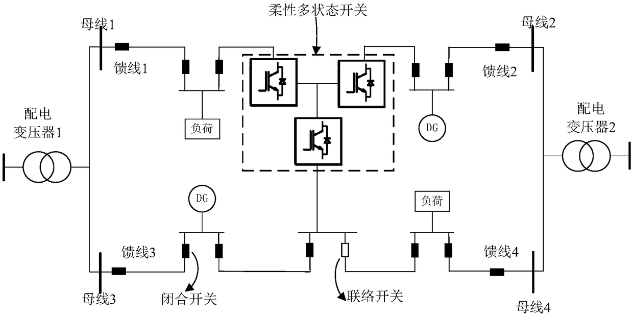
[0022] figure 1 Shown is the main application object of the present invention, the flexible multi-state switch connected to the distribution network system. The system includes distribution transformers, busbars and multiple feeders. Loads and distributed power sources DG are connected to different feeders through closed switches. Different feeders are interconnected through tie switches or flexible multi-state switches FMSS, which can be realized through the interconnection of flexible multi-state switches FMSS Different feeder closed-loop operation and flexible control and transfer of power flow between feeders, thereby promoting the equalization of load distribution among feeders and the improvement of power quality.

[0023] The method for optimizing the design of the flexible multi-state switch connected to the distribution network of the...


PUM


Abstract

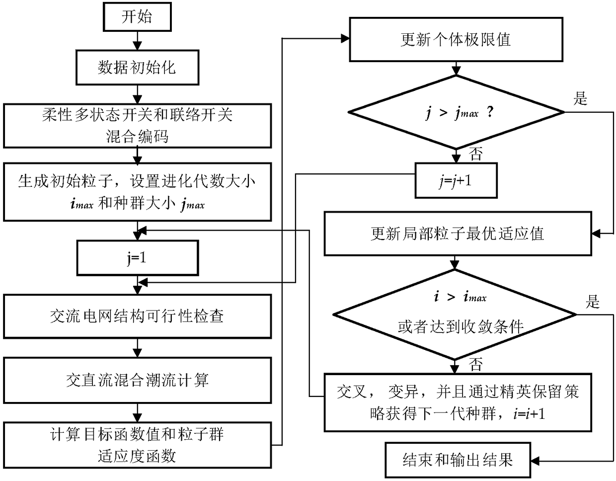
Provided in the invention is a design method for access of a flexible multi-state switch to a distribution network. On the basis of simulation of a multi-scene power flow, distribution network weak positions including distribution network node voltage limiting exceeding and line load heavy loading and the like after access of a distributed power source are calculated and analyzed and a flexible multi-stage switch access location is determined; a system optimization model of access of the flexible multi-stage switch to the distribution network using economic cost minimization as an objective function is established, wherein the objective function includes a yearly conversion cost and a system operation loss cost of initial investment of the flexible multi-stage switch and various constraintconditions are met; with an improved particle swarm optimization method based on a genetic algorithm (GA-PSO), an optimization design model including discrete variables and continuous variables of the flexible multi-state switch is calculated, mixed coding is carried out on the complicated discrete variables and continuous variables, and crossover and mutation operations of the genetic algorithmare introduced into a particle swarm optimization method for improvement; and thus an optimization design plan for access of the flexible multi-state switch to the distribution network is obtained byoptimization calculation.

Description

technical field [0001] The invention relates to a design method for connecting a flexible multi-state switch, in particular to an optimal design method for connecting a flexible multi-state switch to a distribution network. Background technique [0002] The flexible multi-state switch adopts the new technology of power electronics, which not only has two states of on and off, but also adds a continuous controllable state of power. It is the key supporting equipment in the future smart distribution network to solve problems such as power supply interruption and ring closure impact, and at the same time, it can promote the equalization of feeder load distribution and the improvement of power quality. However, at present, the main research work on flexible multi-state switches is focused on the research and development of devices, topology design, operation control, and integration testing. Most of them are manually designed with engineering experience, and the location and ca...

Claims


Application Information

Patent Timeline
Patent Type & Authority Applications(China)
IPC IPC(8): H02J3/06
CPCH02J3/06
Inventor 杨艳红裴玮张释中许烽陆翌王朝亮
Owner INST OF ELECTRICAL ENG CHINESE ACAD OF SCI
Learn More