Washstand
A washstand and wall technology, applied in the field of washstands, can solve problems such as easy generation of odor, inability to place supplies, falling, etc., and achieve the effects of removing water vapor and peculiar smell, preventing cabinets from falling, and removing water vapor.
- Summary
- Abstract
- Description
- Claims
- Application Information
AI Technical Summary
Problems solved by technology
Method used
Image

Examples
Embodiment
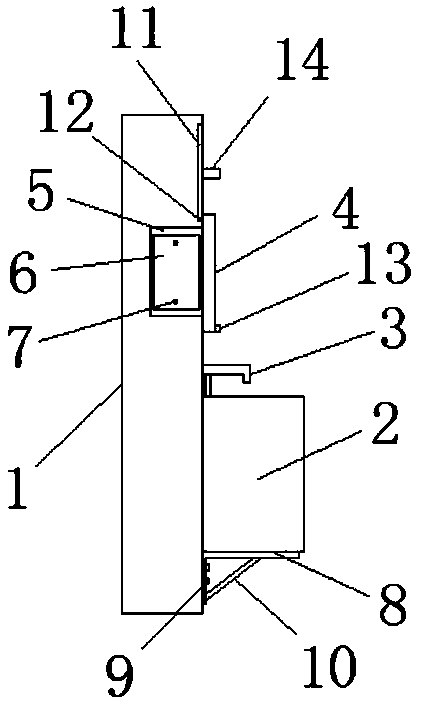
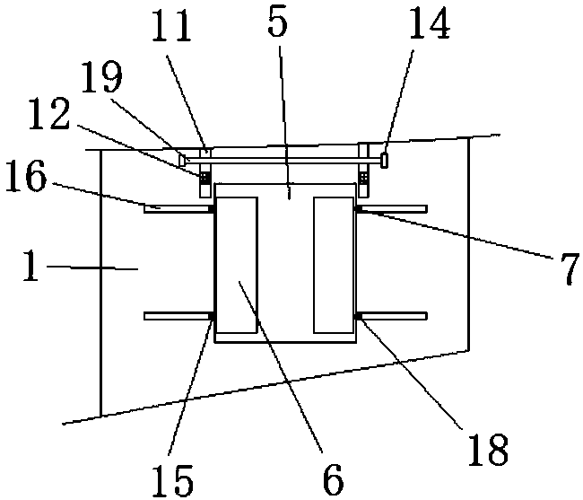
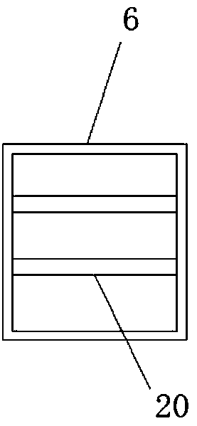
[0028] refer to Figure 1-7 , a washstand, comprising a wall 1, a cabinet 2 and a mirror 4, a cabinet 2 is installed on the surface of the wall 1, a mirror 4 is installed on the upper end of the cabinet 2, and the top of the cabinet 2 A water tap 3 is installed, and the surface of the wall 1 is provided with a placement groove 5, and the inner cavity of the placement groove 5 is equipped with a placement box 6 and the number of placement boxes 6 is two groups, and the back of the placement box 6 is up and down. Connecting block 7 is installed, and the lower end of the surface cabinet body 2 of described body of wall 1 is equipped with tripod 8, and the left side wall of described tripod 8 is fixedly connected with body of wall 1 by bolt 9, and the two side walls of described tripod 8 pass through The reinforcing rib 10 is fixedly connected, the surface of the mirror 4 is equipped with a handle 13, and both sides of the upper end of the mirror 4 on the surface of the wall 1 are...
PUM
 Abstract
Description
Claims
Application Information
PatSnap Eureka turns technology decisions into work you can execute. Powered by our Innovation Knowledge Graph, it runs expert workflows across engineering, life sciences, materials and intellectual property. Get your review-ready output in minutes.


