

Stirring device
A stirring device and mixing barrel technology, applied in mixers with rotating stirring devices, transportation, packaging, dissolution, etc., can solve the problems of long processing cycle, complicated process, low work efficiency, etc., achieve good effect, prevent clogging, The effect of improving stirring efficiency
Active Publication Date: 2018-07-24
青岛泰富科技有限公司
View PDF5 Cites 12 Cited by
- Summary
- Abstract
- Description
- Claims
- Application Information
AI Technical Summary
Problems solved by technology
The whole process is complicated and the processing cycle is long, resulting in low work efficiency
Method used
View moreImage
Smart ImageViewing Examples

Examples
Embodiment Construction
[0013] The present invention will be described in further detail below by means of specific embodiments:
Login to View More PUM
 Abstract
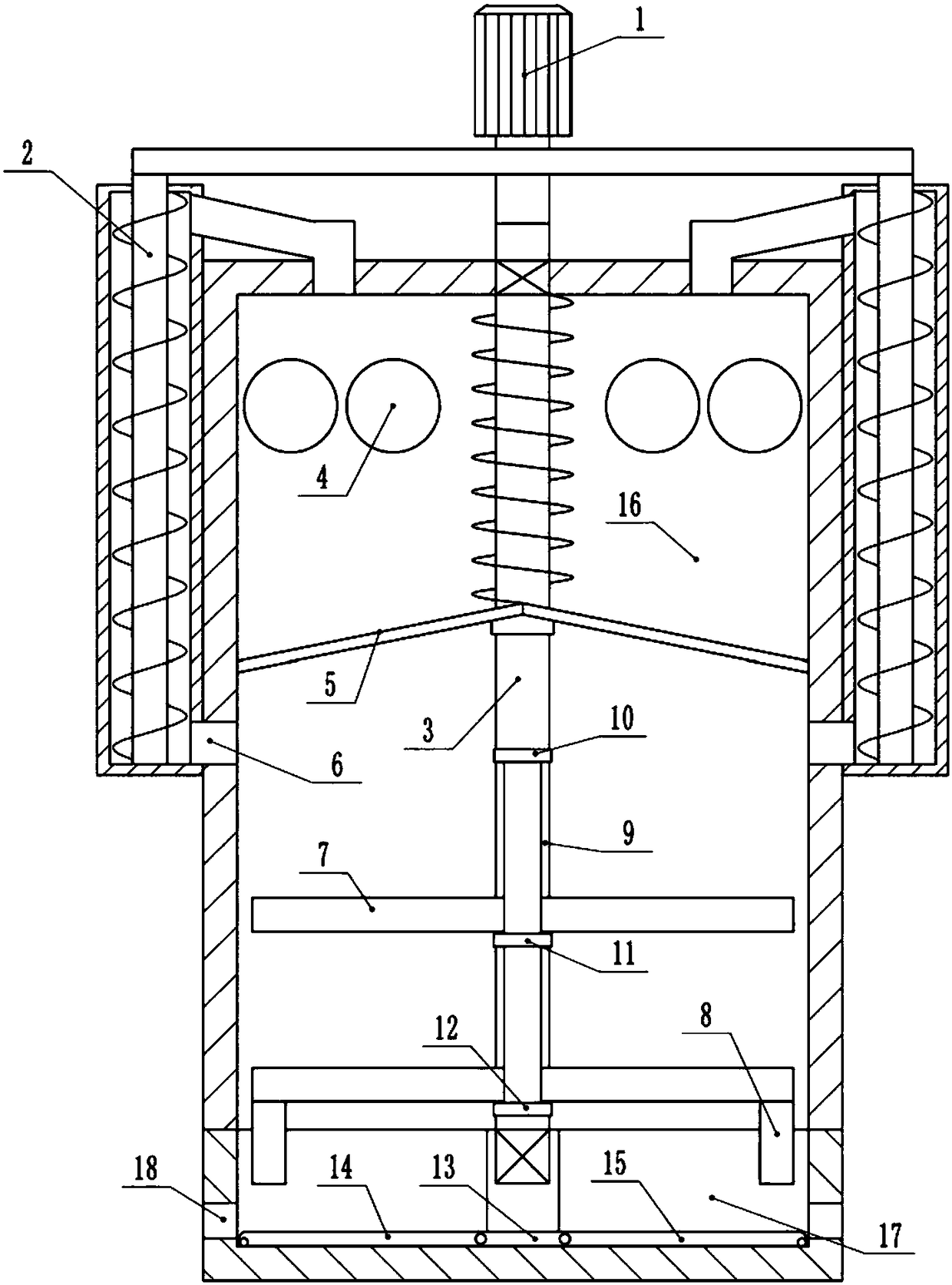
The invention belongs to the technical field of stirring equipment and in particular discloses a stirring device. The stirring device comprises a stirring barrel and a charging basket, wherein a motoris arranged on the stirring barrel; a rotating shaft is connected onto an output shaft of the motor; the lower end of the rotating shaft is rotationally connected into the charging basket; two feeding holes are formed in top walls of the stirring barrel; two grinding roller groups are arranged in the stirring barrel; a spring is arranged on the rotating shaft in a sleeving manner; the upper end of the spring is fixed on the top wall of the stirring barrel; a screen is arranged at the lower end of the spring and connected onto the inner wall of the stirring barrel in a sliding manner; a chuteis formed in a side wall of the rotating shaft; two upper and lower layers of stirring paddles are connected onto the chute in a sliding manner; a first electromagnet, a second electromagnet and a third electromagnet are sequentially arranged at the top end, in the middle and at the lower end of the chute; permanent magnets are arranged on the screen and the two groups of stirring paddles; the left and right sides of the screen are downwards inclined; circulating orifices are formed in side walls on two sides of the stirring barrel; screw feed mechanisms are arranged outside the circulating orifices; orifices in the upper ends of the two screw feed mechanisms are respectively communicated with the two feeding holes.
Description
technical field [0001] The invention belongs to the technical field of stirring equipment, and in particular relates to a stirring device. Background technique [0002] At present, in the chemical industry, when materials need to be mixed and stirred, it is usually necessary to use a stirring device to mix and stir the materials so that the materials can react better during the mixing and stirring. Therefore, the stirring device is widely used in petroleum, chemical industry , rubber, pesticides, dyes, medicine and food industries. Among them, the stirring device usually extends its stirring structure into the mixing barrel, and puts materials into the mixing barrel, and the stirring and mixing operation of the materials through its stirring structure can achieve the effect of accelerating the reaction of the materials or making the materials evenly mixed. However, the existing stirring device still has the problem of low stirring efficiency. Moreover, the raw materials ne...
Claims
Login to View More Application Information
Patent Timeline
 Patent Type & AuthorityApplications(China)
IPC IPC(8): B01F7/00B01F7/16B01F7/18B01F7/24B01F11/00B01F13/08
CPCB01F27/074B01F27/806B01F27/92B01F27/90B01F31/441B01F33/4535
Inventor李小琼
Owner青岛泰富科技有限公司