Graphite lubricating device of stopper for metallurgy casting
A graphite lubricating and blocking technology, applied in the field of metallurgical casting, can solve the problems of poor quality of casting products, ineffective blocking, insensitive opening and closing, etc., and achieve the effect of good high temperature environment and high reliability
- Summary
- Abstract
- Description
- Claims
- Application Information
AI Technical Summary
Problems solved by technology
Method used
Image
Examples
specific Embodiment approach 1
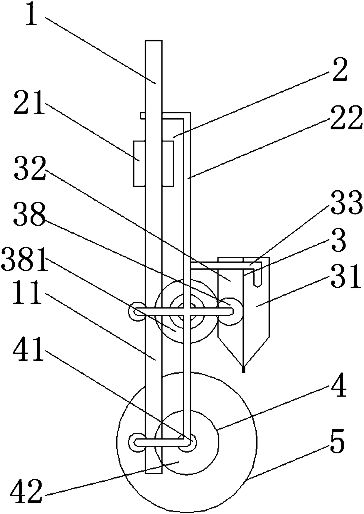
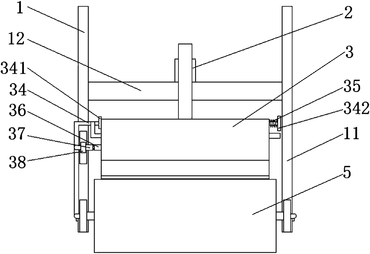
[0061] combine figure 1 and figure 2 As shown, a graphite lubricating device for metallurgical casting blocks disclosed in this embodiment includes: a frame 1, a lifting mechanism 2, an ink spreading mechanism 3 and a block turning mechanism 4, and the upper end of the frame 1 is fixed to the wall End connection, the frame 1 is provided with a lifting mechanism 2, the lifting end of the lifting mechanism 2 is fixedly connected with the ink spreading mechanism 3, a stopper 5 is set under the ink spreading mechanism 3, and the side of the stopper 5 is connected with the stopper turning mechanism 4 , the block turning mechanism 4 is fixedly connected with the frame 1;
[0062] When the stopper 5 is blocked, the lifting mechanism 2 drives the stopper 5 to move downward, while the stopper turning mechanism 4 makes the stopper 5 turn over while moving downwards, and the ink spraying mechanism 3 is on the outside of the stopper 5 in the process of turning over. Ink is sprinkled on...
specific Embodiment approach 2
[0072] This implementation mode is based on the specific implementation mode 1, combining Figure 5 As shown, the difference is that the top of the fixed ink cartridge 31 or the vibrating ink cartridge 32 is hinged with an ink cartridge cover.
[0073] As the vibrating cartridge is subjected to repeated vibrations, the graphite powder is splashed by implementing the cartridge cover.
specific Embodiment approach 3
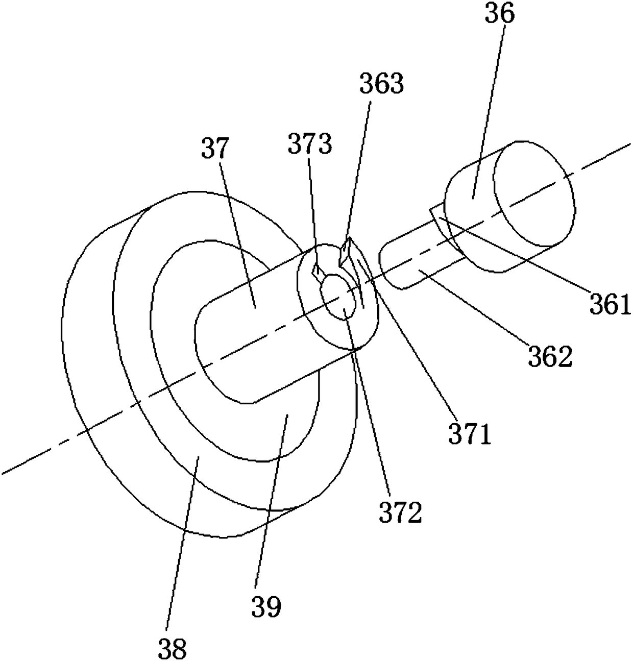
[0074] This implementation mode is based on the specific implementation mode 1, combining figure 1 and image 3 As shown, the difference is that the transmission gear 38 is internally sleeved with a one-way bearing 39, the outer ring of the one-way bearing 39 is fixedly connected with the transmission gear 38, and the inner ring of the one-way bearing 39 is fixedly connected with the vibrating cartridge vibration block B37 , the anti-rotation direction of the one-way bearing 39 is counterclockwise;
[0075] When the stopper 5 moves upwards, there is no need to spray ink. At this time, the auxiliary gear 381 rotates counterclockwise, which drives the transmission gear 38 to rotate clockwise. The one-way bearing 39 allows rotation in the clockwise direction, and the vibration of the ink cartridge vibration block B37 does not occur. Turn, the vibrating ink cartridge stops vibrating, and the ink spreading mechanism stops ink spreading, which realizes that ink spreading is not per...
PUM
 Abstract
Description
Claims
Application Information
 - R&D
- Intellectual Property
- Life Sciences
- Materials
- Tech Scout
- Unparalleled Data Quality
- Higher Quality Content
- 60% Fewer Hallucinations
Browse by: Latest US Patents, China's latest patents, Technical Efficacy Thesaurus, Application Domain, Technology Topic, Popular Technical Reports.
© 2025 PatSnap. All rights reserved.Legal|Privacy policy|Modern Slavery Act Transparency Statement|Sitemap|About US| Contact US: help@patsnap.com


